UNIT-5
Hydraulic accumulator
Accumulators usually are installed in hydraulic systems to store energy and to smooth out pulsations. Typically, a hydraulic system with an accumulator can use a smaller pump because the accumulator stores energy from the pump during periods of low demand. This energy is available for instantaneous use, released upon demand at a rate many times greater than what could be supplied by the pump alone.
|
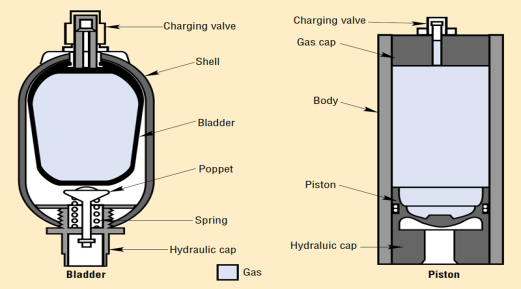
Fig 1
Accumulators also can act as surge or pulsation absorbers, much as an air dome is used on pulsating piston or rotary pumps. Accumulators will cushion hydraulic hammer, reducing shocks caused by rapid operation or sudden starting and stopping of power cylinders in a hydraulic circuit.
There are four principal types of accumulators: the weight-loaded piston type, diaphragm (or bladder) type, spring type, and the hydro-pneumatic piston type. The weight-loaded type was the first used, but is much larger and heavier for its capacity than the modern piston and bladder types. Both weighted and spring types are infrequently found today. Hydro-pneumatic accumulators, Figure 1, are the type most commonly used in industry.
Energy storage — Hydro pneumatic accumulators incorporate a gas in conjunction with a hydraulic fluid. The fluid has little dynamic power-storage qualities; typical hydraulic fluids can be reduced in volume by only about 1.7% under a pressure of 5,000 psi. (However, this relative incompressibility makes them ideal for power transmission, providing quick response to power demand.) Therefore, when only 2% of the total contained volume is released, the pressure of the remaining oil in the system drops to zero.
On the other hand, gas, the partner to the hydraulic fluid in the accumulator, can be compressed into small volumes at high pressures. Potential energy is stored in the compressed gas to be released upon demand. Such energy can be compared to that of a raised pile driver ready to transfer its tremendous energy upon the pile. In the piston type accumulator, the energy in the compressed gas exerts pressure against the piston separating the gas and hydraulic fluid. The piston in turn, forces the fluid from the cylinder into the system and to the location where useful work will be accomplished.
Pulsation absorption - Pumps, of course, generate the required power to be used or stored in a hydraulic system. Many pumps deliver this power in a pulsating flow. The piston pump, commonly used for its high pressure capability, can produce pulsations detrimental to a high-pressure system. An accumulator properly located in the system will substantially cushion these pressure variations.
Shock cushioning - In many fluid power applications, the driven member of the hydraulic system stops suddenly, creating a pressure wave that travels back through the system This shock wave can develop peak pressures several times greater than normal working pressures. It can cause objectionable noise or even system failure. An accumulator's gas cushion, properly located in the system, will minimize this shock.
An example of this application is the absorption of shock caused by suddenly stopping the loading bucket on a hydraulic front end loader. Without an accumulator, the bucket, weighing over 2 tons, can completely lift the rear wheels of a loader off the ground. The severe shock to the tractor frame and axle, as well as operator wear and tear, is overcome by adding an adequate accumulator to the hydraulic system.
Supplementing pump flow - An accumulator, capable of storing power can supplement the hydraulic pump in delivering power to the system. The pump stores potential energy in the accumulator during idle periods of the work cycle. The accumulator transfers this reserve power back to the system when the cycle requires emergency or peak power. This enables a system to utilize a much smaller pump, resulting in savings in cost and power.
Maintaining pressure - Pressure changes occur in a hydraulic system when the liquid is subjected to rising or falling temperatures. Also, there may be pressure drop due to leakage of hydraulic fluid. An accumulator compensates for such pressure changes by delivering or receiving a small amount of hydraulic fluid. If the main power source should fail or be stopped, the accumulator would act as an auxiliary power source, maintaining pressure in the system.
Fluid dispensing - An accumulator may be used to dispense small volumes of fluids, such as lubricating greases and oils, on command.
The optimum mounting position for any accumulator is vertical with the hydraulic port down. Piston models can be horizontal if the fluid is kept clean. When solid contaminants are present or expected in significant amounts, horizontal mounting can result in uneven or accelerated seal wear. Maximum service life can be achieved in the horizontal position with multiple piston seals to balance the piston's parallel surface.
|

Fig 2 Horizontally mounted accumulators can cause uneven bladder wear and trap fluid away from the hydraulic valve.
A bladder accumulator also can be mounted horizontally, Figure 2, but uneven wear on the bladder as it rubs against the shell while floating on the fluid can shorten life. The amount of damage depends on fluid cleanliness, cycle rate, and compression ratio (defined as maximum-system-pressure/ minimum-system-pressure). In extreme cases, fluid can be trapped away from the hydraulic end, which reduces output or may elongate the bladder to force the poppet closed prematurely.
Accumulators are also used for systems where thermal expansion could cause excessive pressure. Cylinders with blocked ports in a high ambient heat area can go to high pressure if there is no place for expanding fluid to go.
Another use for accumulators is as a barrier between two different fluids. The pump that uses hydraulic fluid keeps pressure on a circuit that uses water or another incompatible medium. One supplier offers low-pressure accumulators as breathing devices for sealed reservoirs. This keeps airborne contaminants out of the hydraulic oil as the fluid level rises and falls.
Key takeaways:
1) Accumulators are also used for systems where thermal expansion could cause excessive pressure
2) A hydraulic system with an accumulator can use a smaller pump because the accumulator stores energy from the pump during periods of low demand
The hydraulic intensifier is a mechanical device which is used to increase the intensity of pressure of the fluid. It utilizes the energy of large quantity of liquid at low pressure. Some hydraulic machines require high pressure for working but this high pressure can’t be obtained by using pump. Some of these hydraulic machines are hydraulic press, hydraulic ram and hydraulic lift etc. These machines require high pressure for this operation to obtain the required amount of pressure. A hydraulic intensifier is mounted in between the pump and the working machine. It has two types one is single acting and other is double acting. Here we will discuss the only single acting hydraulic intensifier i.e. it supplies high pressure liquid during the downward stroke only. The double acting hydraulic intensifier supplies high pressure in both strokes i.e. in continuous manner. Generally a normal intensifier can raise the pressure intensity of liquid at 150-160 MN/.
CONSTRUCTION:
A hydraulic intensifier is very simple in construction; it has only three main parts, these parts are attached in a proper sequence for increasing the pressure of input fluid. These three main parts are fixed ram, sliding cylinder or ram and a fixed cylinder.
|
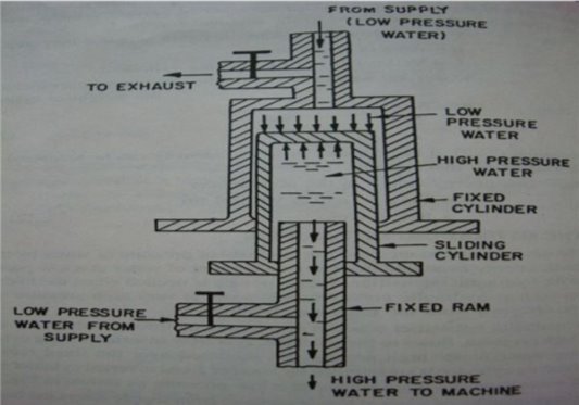
Fig 3
- Fixed Cylinder: It is the outermost body part of the hydraulic intensifier. The low pressure liquid comes into the fixed cylinder from the main supply. The sliding cylinder or ram is slides inside the fixed cylinder.
2. Sliding Cylinder or Ram: It is the middle part of hydraulic intensifier i.e. it slides in between the fixed ram and fixed cylinder. This is the only moving part of this device. It slides under the action of hydraulic force. Sliding cylinder contains high pressure liquid which is supplied to it through the fixed ram.
3. Fixed Ram: It is the inner most and smallest part of the hydraulic intensifier. It is surrounded by a sliding cylinder. The high pressure liquid is supplied to the machine through this fixed ram.
4. Valve: Hydraulic intensifier consists of four valves for easy understanding we can name them A, B, C and D. ‘A’ and ‘D’ allows low pressure liquid from the supply into the device. The liquid comes in from valve ‘D’ goes into the fixed cylinder and the liquid goes in through the valve ‘A’ goes into the sliding cylinder. Valve is for exhaust purpose i.e. it permits the low pressure liquid from the fixed cylinder to be discharged to exhaust. The valve ‘B’ is used to supply high pressure liquid to the outlet of intensifier which is attached with hydraulic machines.
As discussed above hydraulic intensifier is used to increase the intensity of fluid pressure. Its working based upon the fluid movement in it. The liquid from low pressure comes in and at high pressure goes out to the machine or outlet. In the starting movement the sliding cylinder is at its rest position i.e. at bottom most position. Now the liquid of low pressure comes into the fixed cylinder through valve ‘D’ and fill it properly. Now the valve C, B and D are closed. The only valve ‘A’ is opened which permits the low pressure liquid into the sliding cylinder or ram. After that the valve ‘C’ is opened which permits the low pressure liquid from the fixed cylinder to be discharged to exhaust. When the low pressure comes out from the fixed cylinder then the sliding cylinder starts moving upwards due to the supply from valve ‘A’. When the sliding cylinder reaches the topmost position then this sliding cylinder is filled with low pressure liquid. The valves ‘A’ and ‘C’ are closed when the sliding cylinder completely filled with low pressure liquid. Now the valves ‘B’ and ‘D’ are opened, the low pressure liquid from the supply i.e. through valve ‘D’ enters into the fixed cylinder which pushes the sliding cylinder to move downwards which results high pressure liquid is produced in the sliding cylinder. This high pressure liquid is supplied to the required output or to the some hydraulic machinery. High pressure liquid is comes out from the valve ‘B’. This cycle is repeated continuously and low pressure liquid comes out with high pressure intensity.
- Hydraulic intensifier is used to supply high intensity pressure where ever need.
- It used where pump is not sufficient to provide high intensity of pressure as per the requirement.
- It is most commonly used in hydraulic press, hydraulic ram, hydraulic cranes and hydraulic lifts etc. where high intensity of pressure is required for lift the loads.
- Hydraulic intensifier is a compact device and very easy to operate and control.
- It can be directly attached with the hydraulic machinery, where ever it is needed.
- It is compact as well as energy saving device.
- It is cheaper device if we looks about its working, it save lot of money by their easy and economical operation. We can say that it is simple in working, safe and economical in operations.
- It has high speed operation due to this it can be easily starts and stop as per our requirements.
- It can easily works with the pump, that’s why it may be attached in between the pump and the hydraulic machinery.
- It is very easy to operate and control.
- It provides constant force and pressure in whole working process.
- The main disadvantage of the hydraulic intensifier is same which mostly occurs in case of the all other hydraulic systems i.e. leakage of the fluid.
- Sometimes the hydraulic fluid used is may be corrosive which damage the out machinery.
- The other main disadvantage is of leakage fluid can catch fire so the working should be done in proper manner and try to avoid the any small leakage of the fluids.
- This system requires high maintenance.
Key takeaways
1) The hydraulic intensifier is a mechanical device which is used to increase the intensity of pressure of the fluid
2) Generally a normal intensifier can raise the pressure intensity of liquid at 150-160 MN/.
A hydraulic press uses a hydraulic cylinder to produce a compressive force. Within a hydraulic press, there is a plate where the sample is placed to be pressed for sample preparation.
Working Principle of a Hydraulic Press
A hydraulic press works on the principle of Pascal’s law, which states that when pressure is applied to a confined fluid, the pressure change occurs throughout the entire fluid. Within the hydraulic press, there is a piston that works as a pump that provides a modest mechanical force to a small area of the sample. There is also a piston with a larger area, which produces a larger mechanical force.
Pascal's Law is a theory which states that the pressure (P) in a confined fluid, caused by a force (F1), over an area (A1), is transmitted undiminished, causing a force (F2), over the area (A2). This law can be applied to magnify a small force by the ratio of the areas to give a larger force – F2 = F1 (A2/A1).
|
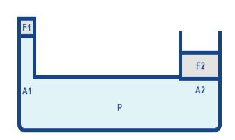
Fig 4
In a hydraulic press, a modest mechanical force (F1) is applied to a small area (A1). As the fluid is moved in one location, it inevitably moves elsewhere within that channel. Then a larger area (A2) generates a magnified mechanical force (F2). The force is transmitted via hydraulic pressure generated by the initial effort, F1.
|

Fig 5
Application areas are almost limitless. Usually, a laboratory hydraulic press will be used to prepare samples for analysis by compressing them into pellets or thin films. The particles are forced together, creating a homogenous sample ideal for spectroscopic examination.
Applications of Hydraulic Press
- Aerospace industry
- Automotive parts
- Thermoplastic Industries
- Carbon Fiber Molding
- Glass Mat Transfer (GMT)
- Resin Transfer Molding (RTM)
- Sheet Molded Composites (SMC)
- Metal forming operations
- Deep drawing operations
- Punching operations
- Blanking operations
- Moulding operations
- Clinching operations
- Forging operations
On the basis of structure hydraulic press can be of following types.
- Universal hydraulic press
- Vertical frame hydraulic press
- Horizontal hydraulic press
- Single column hydraulic press
- Four-column hydraulic press
- Built-in overload protection
- It is safe compared to mechanical press
- It is compact
- Lower tool cost due to built-in overload protection
- It is quiet in operation
- Greater versatility compared to mechanical press
- Lower initial and operating cost
- It offers a full power stroke
Disadvantages of Hydraulic Press
Although Hydraulic presses have large number of advantages but there are some disadvantages too.
- Handling of hydraulic oil can be messy
- Hydraulic lines could burst due to excess pressure
- Some hydraulic fluids can catch fire
- There are chances of hydraulic fluid leakage
- System gets heated because the hydraulic fluid is forced through the pumps
- It has low operational speed
- They have relatively high energy consumption
Key takeaways
1) A hydraulic press uses a hydraulic cylinder to produce a compressive force.
2) A hydraulic press works on the principle of Pascal’s law, which states that when pressure is applied to a confined fluid, the pressure change occurs throughout the entire fluid
5.4 Hydraulic crane
Mobile cranes are specifically designed for transporting different types of loads and cargo with no assembly or setup. A hydraulic mobile crane use hydraulics to lift hundreds and thousands of pounds. The hydraulics relies on forces that are being transmitted through the oil that pushes the pistons of the boom in opposite directions.
Working of a hydraulic mobile crane
Hydraulic cranes work on the concept of transmitting forces from one point to another through a fluid and only due to this they are able to lift the heavy loads. In the essence, a hydraulic crane works on optimizing the strength that is produced by the liquid under pressure. Generally the liquid is water or light oil that works with the system of pistons. These pistons are attached to the system of levers and thereby used to lift heavy loads.
Advantages:
Easy to operate: These cranes are the simplest systems that are used within the industries and are easy to maintain.
Lightweight: Majority of hydraulic cranes are of lightweight but are still capable of lifting heavy loads like the tower crane.
Flexible: The hydraulic cranes can be easily moved from one place to another, they are very flexible to use.
Compact: Unlike the tower cranes, the hydraulic crane does not need larger space to operate.
Hydraulic systems are used for all sorts of things from car braking systems to forklift trucks, presses to pumps. All the systems use the same basic principle, and hydraulic lifts are no different.
The main components of a hydraulic elevator are:
- Piston within a cylinder (called a ram)
- Oil reservoir or tank
- Pump
- Motor (to drive the pump)
- Valve
Usually a hydraulic lift will have a machine room, which will house the pump, fluid and motor, so you may need more space than expected. You can get machine-room-less (MRL) hydraulic lifts which generally house the machinery and such within the shaft, against the guides that run behind the lift, making them a more space-saving option.
Hydraulic Lifts Working
Hydraulic lifts work on a basic principle: to go up, a pump pushes oil into the cylinder, pushing the piston (which pushes the lift car) up. To go down, the valve opens and oil is allowed to flow back into the reservoir, and is pushed back using the gravitational force of the lift car.
When the valve is closed, the oil can only go from the reservoir into the cylinder. When the valve is open, the oil can only flow from the cylinder back into the reservoir. The controls in the lift car make the pump operate, moving the oil. When a floor is reached, the pump is switched off and the lift car sits on top of the piston, held in position by the oil which is trapped in the cylinder.
Even automobile brakes use hydraulics. When you push the brake pedal, it pushes a small piston in the brake master cylinder. The piston applies pressure on the brake fluid, which transfers the pressure through the brake lines, forcing another set of pistons to force the brake linings into contact with the brake drums on each wheel. The resulting friction of brake lining against brake drum slows the car down, eventually stopping the car
The position, size and operation of the cylinder can be one of two options – ‘holed’ or ‘hole-less’
A holed hydraulic lift is a conventional hydraulic lift. ‘Holed hydraulic’ refers to the hole required in the floor for the lift. The cylinder which encases the piston and pushes the lift car extends into the ground. The distance this extends is equal to the distance the lift car can travel upwards.
A hole-less hydraulic lift means no need for a deep pit for the cylinder. The pistons are direct action, and are mounted on the floor of the pit in line with the bottom corners of the lift car. The system operates like a jack, and restricts travel to around 20-30m at most. This is not as common but allows for use where space is restricted going down, travel is short and a hydraulic system is required.
Pros & Cons of Hydraulic Lifts
To help when choosing a lift, it is worth taking into account the benefits and limitations in relation to your requirements. Different environments, travel heights, usage levels and space available can be a deciding factor.
With the machine room holding all the machinery, you won’t need space above the shaft to hold machinery (which traction lifts do). The system is also supported by the floor/pit so should not need any kind of reinforcement.
The classic ‘dead drop’ situation is not possible in a hydraulic lift as there are no cables – though this doesn’t often happen in reality. If the system breaks, then the lift will only drop at the speed which oil can leak from the system.
Finally, hydraulic lifts are cheaper than traction lifts so if budget is key then this could help make the decision.
It is worth looking at the travel distance as a hydraulic lift system is quite slow (up to 1m/s). It may not be suitable over 6-8 floors – also due to requiring further underground space to house the cylinder.
Space required for a machine room and oil pit if required might not be suitable in all buildings, especially where floor space is at a premium. Digging down for holed systems can mean going very deep underground which may not always be possible.
Hydraulic systems rely on the oil, which operates differently at different temperatures (oil gets thinner at higher temperatures) so a good system can help balance this effect.
As with any fluid, oil can leak out of the system which can cause big issues. This doesn’t tend to happen to new systems but keeping your lift maintained properly is vital.
Finally, if you are looking to meet BREEAM or energy efficiency ratings, hydraulic lifts are less energy efficient than other types of lift. The power required to raise the lift car is high, as the oil is doing all the work fighting against gravity. Alternatives, such as traction lifts, use a counterweight so require less energy.
Key takeaways
1) Hydraulic lifts work on a basic principle: to go up, a pump pushes oil into the cylinder, pushing the piston (which pushes the lift car) up. To go down, the valve opens and oil is allowed to flow back into the reservoir, and is pushed back using the gravitational force of the lift car.
2) When the valve is closed, the oil can only go from the reservoir into the cylinder.
3) When the valve is open, the oil can only flow from the cylinder back into the reservoir
The hydraulic ram is a pump which raises water without any external power for its operation. One essential requirement for the satisfactory operation of a hydraulic ram is the availability of a large quantity of water with a small positive head or height. This large quantity of water at a small height is sufficient to lift small quantity of water to a greater height. It works on the principle of “Water Hammer.”
|
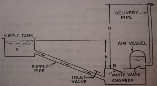
Fig 6
The system has a chamber with two flap valves and an air vessel. This chamber is connected to the water supply from a supply tank or a water reservoir at a small height. The supply tank and the pumping chamber are separated by a valve which controls the flow of water.
|
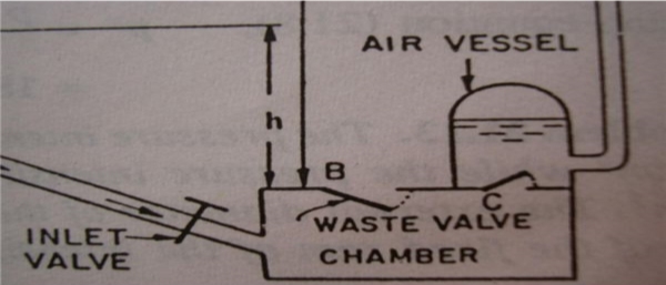
Fig 7
When the inlet valve fitted on the supply line is opened, water starts flowing from the supply tank to the pumping chamber. The chamber has two valves, “B” and “C.” Valve “B” is the waste valve and “C” is called the delivery valve. The valve “C” is fitted to an air vessel. As water is flowing from the supply tank, the chamber gets filled up and valve “B” starts to move upwards. A moment comes, when the valve “B” suddenly closes. This sudden closure of valve “B” creates high pressure inside the chamber. This sudden increase in pressure opens “C” which is the delivery valve. Thus the water from the chamber enters the air vessel and compresses the air inside the vessel. The compressed air exerts a force on water which is inside the air vessel. Thus a small quantity of water is raised to a greater height. As the water in the chamber loses momentum, the waste valve “B” gradually opens in downward direction and flow of water from the supply tank starts flowing to the chamber and the cycle will be repeated
|
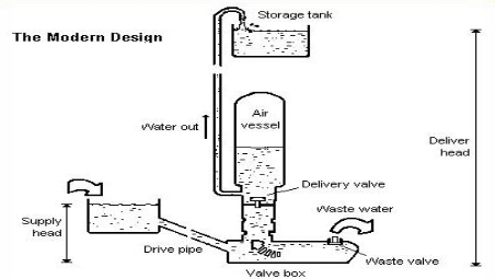
Fig 8
|
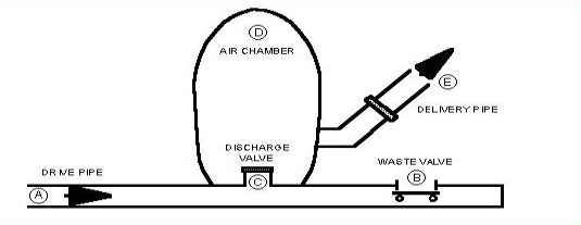
Fig 9
Advantages:
- No moving parts,
- No power requirements,
- Inexpensive,
- Quiet pumping continuously over a long period,
- Pollution free or “Green” pump,
- Simple construction and easy to install, and
- Only initial cost and very low or negligible maintenance cost.
Disadvantages:
- It can pump only one tenth of the received water volume remaining being wasted through waste valve,
- It must have a continuous source of supply at a minimum height of not less than 3 feet or 91 cm.
- It cannot pump viscous fluids to a greater height. Usually used for pumping drinking water or potable water.
W = weight of water flowing per second into the chamber,
w = weight of water raised per second,
h = height of water in supply tank above the chamber,
H = height of water raised from the chamber.
The energy supplied by the supply tank to the ram
= weight of water supplied * Height from which the water is supplied.
= W * h.
Energy delivered by the ram
= Weight of water raised * height through which water is raised.
= w * H.
Thus efficiency = energy delivered by the ram/ energy supplied to the ram
η = w * H/ W * h.
The efficiency η, specified above is called as D’ Aubuisson’s efficiency.
Rankine gave another form of efficiency as he considered that the weight of water raised is not H, but it is (H-h).
Thus Rankine efficiency η = w * (H-h)/ (W-w)* h.
Fluid coupling or hydraulic coupling is also known as hydraulic coupling. It is a hydrodynamic device which is used to transfer rotational power from one shaft to another by the use of transmission fluid. It is used in the automotive transmission system, marine propulsion system, and in industries for power transmission. It is used as an alternative for the mechanical clutch.
It consists of three main components
1. Housing:
It is also known as the shell. It has oil-tight seal around the drive shaft. It also protects the impeller and turbine from outside damage.
2. Impeller or pump:
It is a turbine which is connected to the input shaft and called as impeller. It is also known as pump because it acts as a centrifugal pump.
3. Turbine:
It is connected to the output shaft to which the rotational power is to be transmitted.
The impeller is connected to the prime mover (internal combustion engine) which is a power source. The turbine is connected to the output shaft where rotation power is needed to be transmitted. The impeller and turbine is enclosed in an oil-tight sealed housing. The housing consists of transmission fluid.
The working principle of fluid can be easily explained by the taking two fans in which one is connected to the power supply and other is not. When the power switch is ON, the air from the first fan is starts to blow towards the second fan (which is not connected to the power source). Initially when the first fan is blowing at lower speed, it does not able to drive the second fan. But as the speed of the powered fan increases, the speed of air striking the blades of second fan also increases and it starts to rotate. After some time it acquires the same velocity of that of the first fan.
On the same principle the fluid coupling works. In that the impeller act as first fan and the turbine act as second fan. Both impeller and turbine enclosed in an oil tight housing. The impeller is connected the input shaft of the prime mover and the turbine with the output shaft. When the impeller is moved by the prime mover, the fluid in housing experiences centrifugal force and due to curved vanes of the impeller the fluid directed towards the turbine blades. As the fluid strikes the turbine blades it starts rotating. With the increase in the speed of impeller, the velocity of the turbine increases and becomes approximately equal to the impeller speed. The fluid after passing through the turbine blades again return to the impeller.
|
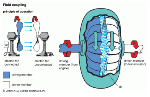
Fig 10
- As the prime mover moves, it rotates the impeller of the coupling. The impeller acts as a centrifugal pump and throws the fluid outward and directs it towards the turbine blade.
- As the high moving fluid strikes the turbine blades, it also starts rotating, after striking on the blades, the direction of the fluid is changed and it is directed towards the impeller again. The blades of the turbine are designed in such a way that it can easily change the direction of the fluid. It is the changing of direction of the fluid that makes the turbine to rotate.
- As the impeller speed increases, the speed of the turbine also increases. After some time the speed of both the impeller and the turbine becomes equal. In this way, power is transmitted from one shaft to another by the use of fluid coupling.
- In same way torque converter works but the difference is that it has stator placed in between impeller and turbine for torque multiplication.
- It is used in automotive industries for the transmission of power from the engine to the wheel as alternative of clutch.
- It is used in marine propulsion systems.
- It is used in various industries for power transmission.
- The power transmission is free from vibration and noises.
- Power transmission is smooth even in extreme condition.
- Overload protection.
- Motor or engine starts unloaded.
- There is always slip. There is always slight difference in speed of impeller and runner.
- Fluid coupling cannot develop torque when the driving shaft and driven shaft are rotating in same angular velocity.
- Under stalling condition, the coupling dissipates energy as heat it may lead to damage.
A torque converter is a type of fluid coupling used for transferring rotating power to the transmission from the motor. It is achieved in an automatic transmission by a hydraulic clutch. The main function is to ensure that the load is separated from the main source of power. It is situated between the motor and the engine. It has the same feature as a handheld clutch. As the clutch separates the engine from the load when it stops, in the same way it also isolates the engine from load and keep engine running when vehicle stops. Its main functions are:
1. It transfers the power from engine to the transmission input shaft.
2. It drives the front pump of the transmission.
3. It isolates the engine from the load when the vehicle is stationary.
4. It multiplies the torque of the engine and transmits it to the transmission. It almost doubles the output torque.
|
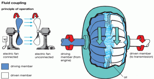
Fig 11
Let's take two fans to grasp the torque converter operating theory. One fan is connected to the power supply and the other is not power supply connected. The air from it moves to the second fan which is stationary when the first fan associated with the power source starts to move. The air of the first ventilator hits on the second fan's blades and also almost at the same pace begins spinning to the first. The first fan starts when the second fan is stopped. The fan continues to revolve.
The torque converter operates according to the same concept. The pump functions as a first ventilator connected to the engine and the generator serves as the second ventilator connected to the transmission system. When the engine is working it rotates the wheel and the oil inside the torque converter is guided to the turbine because of its centrifugal power. The engine starts to spin as it reaches turbine blades. It rotates the transmission system and pushes the vehicle's wheels. The engine also starts spinning when the motor ends, but the drive connected to the motor continues to move and prevents the kill of the motor.
Main Parts
The torque converter has three main parts
|
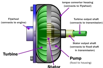
Fig 12
1. Impeller or Pump
The rotor is linked to the cabinet and to the box connected to the motor shaft. It's been bent and twisted. This rotates at motor speed and consists of automatic fluid transfer. The centrifugal force causes the fluid to shift outward when it rotates with the engine. The blades are so designed that the fluid is directed towards the blades of the turbine. It acts as a centrifugal pump which absorbs and transfers the fluid to the turbine through the automatic transmission.
2. Stator
The stator is between the turbine and the impeller. The stator's principal task is to direct the returning fluid out of the turbine to the impeller in the direction of its rotation. When the fluid reaches the impeller stream, the torque is compounded. The stator then helps to increase the torque by changing the direction of the fluid and allows it to reach the direction of rotation of the impeller. The stator shifts almost 90 degrees in the direction of the stream. The stator is installed with a one-way embrace which enables it to rotate in one direction and avoid rotation in another. Turbine is attached to the vehicle's transmission system. And between the turbine and the roller is the stator.
3. Turbine
Turbine is mounted to the automatic transmission input shaft. It's on the side of the car. There are bent and pointed blades as well. The turbine blades are designed so that the direction of the fluid which hits its blades can be modified altogether. The change of direction of the fluid causes the blades to shift towards the impeller. The Turbine also rotates and lets the vehicle shift while the shaft of the motor is spinning. The turbine also has a rear sealing clutch. When the torque converter hits a coupling point, the clutch comes into play. The lock-up eliminates losses and increases the converter's performance.
It has three stages of operations
1. Stall: The engine uses power to the impeller when the vehicle is stall (stop), but the turbine cannot rotate. This is when the car is stationary and the driver has kept his foot on the brake paddle so that it does not move. Maximum torque multiplication takes place during this condition. The impeller moves faster as the driver removes the base from the brake paddle and releases the accelerator paddle, allowing the motor to roll. There is a greater difference in the pump speed from the turbine in this situation. The speed of the rotor is significantly higher than that of the turbine.
2. Acceleration: During acceleration, the speed of the turbine continues to rise, but the impeller and turbine speed also differ greatly. The torque multiplication is decreased as the turbine speed increases. The torque multiplication is less than understanding conditions when the engine is accelerated.
3. Coupling: This happens when the turbine reaches a speed of about 90% of the impeller, which is known as the coupling point. The torque multiplication is null and negative and the torque converter is compared to a simple fluid relation. The locking clutch comes in at the coupling point and locks the turbine to the converter's impeller. This enables the turbine and drives to move at the same speed. Only when the point is reached is the clutch locked up. The stator also begins to rotate towards the rotation of the rotor and of the turbine during the coupling.
1. The maximum torque multiplication takes place during stalling condition.
2. The stator remains stationary before coupling point and helps in the torque multiplication. As the coupling attained, stator stops torque multiplication and starts rotating with the impeller and turbine.
3. Lock up clutch engages when coupling point is achieved and removes the power losses resulting in increased efficiency.
- It produces the maximum torque as compared with the vehicle equipped with clutch.
- It removes the clutch pedal.
- It makes the job of driving a vehicle easier.
- Its fuel efficiency is low as compared with the vehicle with manual transmission.
- The torque converter is used in the vehicle that is equipped with the automatic transmission. It is also used in industrial power transmission such as conveyer drives, winches, drilling rigs, almost all modern forklifts, construction equipment, and railway locomotives.
- It is used in marine propulsion systems.
An air-lift pump is a device which is used to lift water from a well or a sump with the use of compressed air. The compressed air is made to mix with the water. It is well known that the density of water is more than the density of air. So it is obvious and evident that air floats higher than water or to understand better, water has more weight than air. So the main principle used in air-lift pumps is the density difference between water and air. Air is made to mix with the water and thus allowed to form froth. Froth here consists of mixture of water and air. So the density of this mixture is less than that of the water. It is the mixture of air which makes the density less than water. Thus a very small column of pure water can balance a very long column of air-water mixture. This is the working principle of air-lift pumps.
The system has a compressed air pipe with a nozzle introduced into the sump or the well. The compressed air is introduced into one or more nozzles at the foot of the delivery pipe, which is fixed in the well from which water is to be lifted. In the delivery pipe, which is partly open to the well or sump which contains water, a mixture of air and water is formed. As already discussed, this density of air and water becomes less than the density of pure water. Hence a small column of pure water is sufficient to balance a very long column of air-water mixture. This air-water mixture is discharged through the delivery pipe. The flow will continue as long as the compressed air supply is maintained.
|
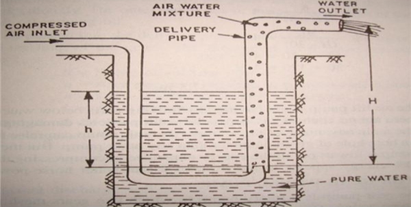
Fig 13
Let us assume
h = height of static water level above the tip of the nozzle,
H = height to which water is lifted above the lip of the nozzle.
Thus (H-h) is known as the useful lift. The results are optimum if the useful lift (H-h) is less than the height of static water (h) above the tip of the nozzle. Hence for best results,
(H-h) < h.
The ratio (h/H-h) generally varies from 4 to 1.
Also when h = 30m, then the ratio (h/H-h) is about 4.
When h = 90m, then the ratio (h/H-h) is about 1.
For h = 30m,
h/H-h =4
So, 30/H-30 = 4
30 = 4H – 120
4H = 150
H = 37.5 m.
For h = 90, h/H-h = 1.
90/H-90 = 1.
90 = H – 90.
H = 180m.
So it is evident that when h increases H also increases.
These pumps do not require any electrical power from the power mains. There are systems installed in villages to irrigate agricultural fields. The system has a windmill which drives an air compressor. The compressed air from the air compressor is led into the pipe which has a nozzle in the deep wells. This system can also be modified by windmill driving a generator and power from this generator is used for compressing air and then used in these pumps.
Advantages
- No moving parts,
- Less maintenance,
- Simple & reliable,
- No mechanical parts below ground level,
- It can handle mud, sand, and gritty water too.
- This pump can raise more water through a bore hole of given diameter than any other pump types.
Disadvantages:
- Worst efficiency, 20 to 30% operating efficiency, when compared to expenditure of energy in compressing air.
- Running cost of an air-lift pump is high in terms of energy expenditure terms.
- Bore holes have to be drilled very deep in order to get enough static head. If not, the discharge will be less and probably no discharge. Boring is considerably a costly operation.
Applications: These pumps, in spite of their poor efficiency, are commonly used in many areas where conventional pumps usage is difficult. These pumps are used in
- Petroleum fields,
- Handling some hazardous liquids,
- Sewage plants,
- Deep sea mining,
- Recovery of archaeological artifact and many more
When the level of underground water becomes quite down we use a Jet pump. Because in that case centrifugal pump or other rotary pumps cannot lift the water from that down level
The working principle of this pump is somewhat different from that of the centrifugal pump or other types of rotary pumps. The working principle of a jet pump depends on the Bernoulli theory.
In a jet pump, water is pushed in a pipe with high pressure. There is a nozzle at the opening of the pipe. The shape of the nozzle is like a cone. When water comes out through the narrow opening of the nozzle with the high pressure the potential energy of the water becomes kinetic energy. Because of that, the pressure surrounds the nozzle reduces. This phenomenon facilitates the section of the inlet water. We have to place the nozzle of the jet pump very nearer to the water level. Then we immerse the suction pipe of the pump in the water.
|
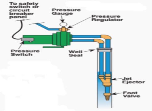
Fig 14
In the industrial Jet pump, instead of using a water jet, we use the steam jet. So, there are two sources of water. The main water comes due to the suction of underground water. The jet water comes from the separate reservoir used to supply the jet water or steam. The total delivery of the jet pump is the summation of these two quantities of water.
Advantages of using a Jet Pump
Jet pumps have several advantages such as:
- No moving parts or mechanical parts that wear.
- Long run life. Providing that erosion is not a major problem, then a working life of at least four years is not unreasonable.
- Capable of high production rates.
- Adjustable to varying production rates by adjusting the power fluid injection rate.
- Low maintenance costs and is easily and quickly retrieved and replaced when maintenance is required.
- The ability to operate for extended periods of time without the need for intervention.
- Power fluid can be sent down the tubing with returns up the annulus (standard circulation) or the power fluid can be sent down the annulus with returns up the tubing (reverse circulation).
- Suitable for low gravity, high pour point crude oils or for controlling paraffin by using reverse circulation with hot water for the power fluid. Chemicals can also be entrained in the power fluid as needed.
- High tolerance to corrosive fluids by the use of CRA materials and/or inhibitors entrained in the power fluid.
- High tolerance to abrasives in the produced fluid.
- Can be used in wells with high deviation angles without causing damage to the tubing.
- Capable of handling high GLR’s.
- The benefits of being able to circulate the down hole pump in and out of the well include reduced downtime and the ability to operate without a pulling unit for tubing, cable, or rod removal.
- Can also be installed in sliding sleeves and nipples using wire line.
- Can also be installed across gas lift mandrels using tubing pack-offs and tubing stops.
- Gages can be installed above and below the jet pump to measure the intake and discharge pressures of the pump, which allows customizing the output of the computer program for a given well.
- Suitable for remote operations.
- Multiple jet pumped wells can be powered by a central surface pump package.
Disadvantages and limitations:’
The disadvantages are:
- Lower efficiencies than other forms of artificial lift resulting in higher horsepower requirements for the power fluid pump (typically the injection rates must be increased due to compensate for the working pressure limits of the system such as the wellhead).
- Power fluid injection rates are typically twice the production rate.
- Space limitations, especially for offshore installations.
- The higher injection rates for the power fluid sometimes result in a higher surface facility investment for handling the volume of fluids returning from the well.
- Backpressure has a pronounced effect on surface injection pressure requirements that varies from approximately 1-1/2 to 1 to approximately 4-1/2 to 1 depending on the area ratio being used.
- High-Pressure Surface Lines
- A jet pump cannot “pump-off” a well. A submergence of approximately 10%, based on the TVD of the location of the jet pump, may be required in order to prevent the problem known as “power fluid cavitation”, which occurs due to the decline in pump-intake-pressure as the well is “pumped-off”.
- A tubing subsurface safety valve is typically employed in any well able to naturally flow to the surface. On some wells, there is also an annular subsurface safety valve. Since there is communication across the jet pump (annulus to tubing and vice versa), then any such safety devices need to be set below the pump in the well. Given that the jet pump is typically set as low (deep) as possible in the well, this creates problems for effective subsurface safety valve deployment.

Applications of Jet Pumps
We often use these pumps during high summer for lifting water from a low underground water level.
We find the maximum uses of jet pumps in oil industries for lifting mineral oil.
References:
1. Hydraulic Machines by Jagdish Lal, Metropolitan book co. pvt ltd.
2. Hydraulic Machines by K Subramanya, Tata McGraw Hill
3. Fluid Mechanics and Machinery by C.S.P.Ojha, R. Berndtsson, P.N. Chandramouli, Oxford University Press
4. Fluid Mechanics and Fluid Power Engineering by D S Kumar, S K Kataria& Sons
5. Fluid Mechanics and Turbo machines by Das, PHI
6. Fluid Power with Applications, by Esposito, Pearson
7. Fluid Mechanics and hydraulic machines by Modi& Seth, Standard Book House
8. Fundamentals of Turbomachinery by Venkanna B.K., PHI
9. Hydraulic Machines: Theory & Design, V.P.Vasandhani, Khanna Pub.
10. Fluid Mechanics and Hydraulic Machines by SukumarPati, Tata McGraw Hill


