Unit -4
Positive Displacement and other Pumps
These pumps are positive displacement pump that is initially a small quantity of liquid is taken into chamber and is physically displaced and forced out with pressure by moving mechanical elements. The use of reciprocating pumps is being limited these days and being replaced by centrifugal pumps. For industrial purpose they have become obsolete due to their high initial establishment and maintenance.
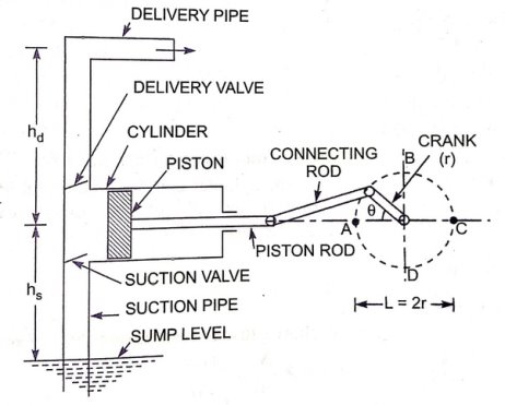
Fig.1: Reciprocating pump Reciprocating pumps consists of a plunger that moves in forward direction as well as in backward direction within the cylinder by using a connecting rod and a crank, which is rotated with the help of an external source of power. The cylinder is connected to the sump through a suction pipe and to the delivery tank by a delivery pipe. At the cylinder ends of these pipes, non-return valves which allow the liquid to pass only in one direction. Liquid in the cylinder is admitted through the delivery valve via suction valve which can be further only discharged into delivery pipes. While movement of piston from left to right direction, a suction pressure is produced by the cylinder. Liquid rises into the suction pipe by a small height due to atmospheric pressure on the sump liquid. During delivery stroke, air in the cylinder is pushed out into the delivery pipe by the thrust of the piston, while the suction valve is closed. When all the air from the suction pipe has been exhausted, the liquid from the sump is able to rise and enter the cylinder. During delivery stroke, it is displaced into delivery pipe. Thus the liquid is delivered into the delivery tank intermittently that is only during the delivery stroke.
Key takeaways: These pumps are positive displacement pump that is initially a small quantity of liquid is taken into chamber and is physically displaced and forced out with pressure by moving mechanical elements.
4.1.1: Discharge through a reciprocating pump: Let, A= Cross sectional area of a cylinder R= crank radius N= rpm of the crank L= stroke length (2r) Discharge through pump per second= Area× stroke length×rpm/60 Qth =A×L×N/60 This will be discharge when the pump will be single acting. And it will be =(2ALN)/60, in case of double acting.
Key takeaways: The important formula for this topic is Qth =A×L×N/60
|
Slip of a Reciprocating Pump Slip of a pump is defined as the difference between the theoretical discharge and actual discharge of the pump. The discharge of a single-acting pump and of a double acting-pump are theoretical discharge. The discharge of a single-acting pump per second is given as - Q = Discharge in one revolution * No. of revolution per second Q = A * L * The discharge of a double acting pump per second is given as – Q = ( Key takeaways-
The actual discharge of a pump is less than the theoretical discharge due to leakage. The difference of the theoretical discharge and actual discharge is known as slip of the pump. Hence, mathematically, Slip = But slip is mostly expressed as percentage slip which is given by, Percentage slip = = (1 - Where
4.2.1: Negative slip of reciprocating pump- Slip is equal to the difference of theoretical discharge and actual discharge. If actual discharge is more than the theoretical discharge, the slip of the pump will become negative. Inn that case, the slip of the pump is known as negative slip. Negative slip occurs when delivery pipe is short, suction pipe is long and pump is running at high speed.
|


The indicator diagram for a reciprocating pump is defined as the graph between the pressure head in the cylinder and the distance travelled by piston from inner dead center for one complete revolution of the crank. As the maximum distance travelled by the piston is equal to the stroke length and hence the indicator diagram is a graph between pressure head and stroke length of the piston for one complete revolution. The pressure head is taken as ordinate and stroke length as abscissa.
4.3.1: Ideal Indicator Diagram- The graph between pressure head in the cylinder and stroke length of the piston for one complete revolution of the crank under ideal condition is known as ideal Indicator diagram. Fig. 2 shows the ideal indicator diagram, in which line EF represents the atmospheric pressure head equal to 10.3m of water.
Fig 2: Ideal Indicator Diagram Let, L = Length of the stroke,
During suction stroke, the pressure head in the cylinder is constant and equal to suction head ( During delivery stroke, the pressure head in the cylinder is constant and equal to the delivery head ( As we know that the work done by the pump per second =
= K * L *( ""
But from fig.4.2, area of indicator diagram =AB * BC = AB * (BF + FC) = L * ( Substitute this value in equation (i), we get Work done by pump Key takeaways: The indicator diagram for a reciprocating pump is defined as the graph between the pressure head in the cylinder and the distance travelled by piston from inner dead center for one complete revolution of the crank. |


The pressure head due to acceleration in the suction pipe is given by equation When When When
Fig. 3: Effect of acceleration on indicator diagram
|


Thus, the pressure head inside the cylinder during suction stroke will not be equal to ‘ ’, as was the case for ideal indicator diagram, but it will be equal to the sum of ‘
 ’.
’.
At the beginning of suction stroke  =
=  , ‘
, ‘ ’ is positive and hence the pressure head in the cylinder will be (
 below the atmospheric pressure head.
At the middle of the suction stroke  =
=  and
and  = 0 and hence pressure head in the cylinder will be
  below the atmospheric pressure head.
At the end of the suction stroke,  is negative and hence the pressure head in the cylinder will be (
 below the atmospheric pressure head.
For suction stroke, the indicator diagram will be shown by A GB
GB . Also, the area of A
 AG = Area of BGB
 .
.
Similarly, the indicator diagram for the delivery stroke can be drawn. At the beginning of delivery stroke,  is positive and hence the pressure head in the cylinder will be (
 above the atmospheric pressure head.
At the middle of the delivery stroke,  and hence the pressure head in the cylinder is equal to
  above the atmospheric pressure head.
At the end of the delivery stroke,  is negative and hence pressure in the cylinder will be (
 above the atmospheric pressure head.
And the indicator diagram for delivery stroke is represented by the line C HD
HD . Also, the area of CC
 H = Area of DD
 H.
H.
From fig.4.3, it is now clear that due to acceleration in suction and delivery pipe, the indicator diagram has changed from ABCD to A B
B C
C D
D . But the Area of indicator diagram ABCD = Area of A
 B
B C
C D
D .
.
Now from equation (ii), work done by pump is proportional to the area of indicator diagram. Hence the work done by the pump on the water remains same.
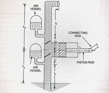
An air vessel is a closed chamber containing compressed air in the top portion and liquid (or water) at the bottom of the chamber. At the base of the chamber there is an opening through which the liquid (or water) may flow in the vessel or out from the vessel. When the liquid enters the air vessel, the air gets compressed further and when the liquid flows out from the vessel, the air will expand in the chamber.
An air vessel is fitted to the suction to the suction pipe and to the delivery pipe at a point closed to the cylinder of a single-acting reciprocating pump:
i. To obtain a continuous supply of liquid at a uniform rate,
ii. To save a considerable amount of water in overcoming the frictional resistance in the suction and delivery pipes, and
iii. To run the pump at a high speed without separation.
Fig. 4: Air vessels fitted to reciprocating pump
|
Centrifugal Pump | Reciprocating Pump
|
The discharge is continuous and smooth. | The discharge is fluctuating and pulsating. |
It can be used for lifting highly viscous liquids. | It is used only for lifting pure water or less viscous liquids. |
It can handle large quantity of liquids. | It handles small quantity of liquid only. |
It is used for large discharge through smaller heads. | It is meant for small discharge and high heads. |
Cost of centrifugal pump is less as compared to reciprocating pump. | Cost of reciprocating pump is approximately four times the cost of centrifugal pump. |
Centrifugal pump runs at high speed. They can be coupled to electric motor. | Reciprocating pump runs at low speed. Speed is limited due to consideration of separation and cavitation. |
The operation of centrifugal pump is smooth and without much noise. The maintenance cost is low. | The operation of reciprocating pump is complicated and with much noise. The maintenance cost is high. |
Centrifugal pump need smaller floor area and installation cost is low. | Reciprocating pump requires large floor area and installation cost is high. |
Efficiency is high. . | Efficiency is low |
It needs priming. | It does not need priming |
No Air vessel is required. | Air vessel is required. |
Uniform torque | Torque is not uniform. |
Centrifugal pump is non-positive displacement type pump. | Reciprocating pump is positive displacement type pump. |
| Centrifugal Pump | Reciprocating Pump |
Pump Characteristics | Steady smooth flow | Flow variation Pulsation suppression device is needed in suction/discharge to avoid excessive vibration on piping. |
Performance at constant speed | Head drop as flow rate increases. Loss of flow rate if system head of requirement are higher than the design point. | Constant flow rate even if pressure increases. Constant flow rate is system head point is higher that design point.
|
Efficiency | Efficiency loss: hydraulic, volumetric and mechanical. Efficiency changes as flow rate or head changes. | Efficiency loss: volumetric, mechanical. Efficiency keeps constant. |
References:
- A text book by R K Bansal on fluid mechanics and machinery
- Google website and online presentations


