Unit-3
Centrifugal Pumps
- According to the types of stages:
- Single stage pumps:
- It is known as single impeller pump.
- It is simple in design and easy in maintenance.
- It is ideal for large flow rates and low pressure installations.
- Two stage pump:
- It has two impellers operating side by side.
- It is used for medium use applications.
- Multistage Pumps:
- It has three or more impellers in series.
- They are used for high head applications.
- Single stage pumps:
- According to the type of case – split:
- Axial split:
- In these types of pumps the volute casing is split axially and split line at which the pump casing separates is at the shaft’s centre – line.
- Radial split:
- In it pump case is split radially, the volute casing split is perpendicular to shaft centre line.
- Axial split:
- According to the types of impeller design.
- Single suction:
- It has single suction impeller which allows fluid to enter blades only through a single opening.
- Double Suction:
- It has double suction impeller which allows fluid to enter from both the sides of blades.
- They are most common types of pumps.
- Single suction:
- According to the type of volute:
- Single volute pump:
- It is usually used for low capacity pumps, as it has small volute size.
- Double volute pump:
- It has two volutes which are placed 180 degrees apart.
- It has a good capability of balancing radial loads.
- Single volute pump:
- According to the shaft orientation:
- Horizontal Centrifugal pumps:
- It is suitable for low pressure.
- Vertical Centrifugal pumps:
- It can easily withstand higher pressure loads.
- It is more expensive than horizontal pumps.
- Horizontal Centrifugal pumps:
- In case of the centrifugal pump, work is done by the impeller on the water.
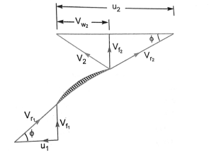
- The expression for the work done by the impeller on the water is obtained by drawing velocity triangles at inlet and outlet of the impeller.
- The water enters the impeller radially at inlet for best efficiency of the pump, which means the absolute velocity of water at inlet makes an angle of 90° with the direction of motion of the impeller at inlet. Hence angle
 and
and  .
. - Figure shows the velocity triangles at the inlet and outlet tips of the vanes fixed to an impeller,
|

Let, N= speed of the impeller in r.p.m
 Diameter of impeller at inlet
 Tangential velocity of impeller at inlet=
 Diameter of impeller at Outlet
 Tangential velocity of impeller at outlet=
 Absolute velocity of water at inlet
 Relative velocity of water at inlet
 = Angle made by absolute velocity
  at inlet with the direction of motion of vane
 = Angle made by relative velocity (
 at inlet with the direction of motion of vane and
  are the corresponding values at outlet.
A centrifugal pump is the reverse of a radially inward flow reaction turbine. But in case of radially inward flow reaction turbine, the work done by the water on the runner per second per unit weight of water striking per second is given by equation

Work done by the impeller on the water per second per unit weight of water striking per second = - [work done in case of turbine]


Work done by impeller on water per second

Where W = weight of water=.  ×g×Q
×g×Q
Where Q= Volume of water
And, Q= Area × velocity of flow =
Where  are width of impeller at inlet and outlet and
  velocity of flow at inlet and outlet
In case of a centrifugal pump, the power is transmitted from the shaft of the electric motor to the shaft of the pump and then to the impeller. From the impeller, the power is given to the water. Thus power is decreasing from the shaft of the pump to the impeller and then to the water. The following are the important efficiencies of a centrifugal pump:
a) Manometric efficiency, ηman
b) Mechanical efficiency, ηm and
c) Overall efficiency, ηo
a) Manometric efficiency, (ηman) The ratio of the manometric head to the head imparted by the impeller to the water is known as manometric efficiency. Mathematically, it is written as
ηman = 
= 
The power at the impeller of the pump is more than the power given to the water at outlet of the pump. The ratio of the power given to water at outlet of the pump to the power available at the impeller, is known as manometric efficiency.
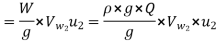
The power given to water at outlet of the pump = 
The power at the impeller = 
= 
ηman = 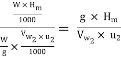
b) Mechanical Efficiency (ηm) The power at the shaft of the centrifugal pump is more than the power available at the impeller of the pump. The ratio of the power available at the impeller to the power at the shaft of the centrifugal pump is known as mechanical efficiency. It is written as
ηm = 
The power at the impeller in kW = 
= 
ηm = 
where S.P. = Shaft power.
c) Overall Efficiency (ηo) It is defined as ratio of power output of the pump to the power input to the pump. The power output of the pump in kW
 =
= 
Power input to the pump = Power supplied by the electric motor
= S.P. of the pump.
∴ ηo = 
Also ηo = ηman × ηm
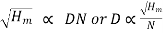
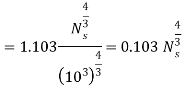
- The specific speed of a centrifugal pump is defined as the speed of a geometrical similar pump which would deliver 1 cubic metre of liquid per second against head of 1 metre. It is denoted by

Expression for specific speed for a pump
The discharge Q for a centrifugal pump is given by the relation
Q= Area ×velocity of flow

D= diameter of the Impeller of the pump
B = width of the impeller
We know that B D
D
From equation (i) we have

We also know that tangential velocity is given by

Now the tangential velocity (u) and velocity of flow  are related to the manometric head
  as
as

Substituting the value of u in equation (iii) we get
Substituting the values of D in equation (ii)


Where K is constant of proportionality
If, 
Substituting these values in equation (v) we get


Substituting the value of K in equation (v) we get


- In centrifugal pumps the cavitation may occurs at the inlet of the impeller of the pump, or at the suction side of the pump, where the pressure is considerably reduced.
- Hence if the pressure at the suction side of the pump drops below the vapour pressure of the liquid then the cavitation occur.
- The cavitation in a pump can be noted by a sudden drop in efficiency and head.
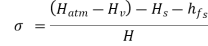
- In order to determine whether cavitation will occur in any portion of the suction side of the pump the critical value of Thoma’s cavitation factor
 is calculated.
 - Thoma’s cavitation factor is used to indicate whether cavitation will occur in pumps. Equation give the value of Thoma’s cavitation factor for pumps as
but we have
|


- If the value of
 (calculated from above equation ) is less than the critical value
  ,then cavitation will occur in the pumps.
 - The value of
 Depends upon the specific speed of pump
  .
. - The following empirical relation is used to determine the value of


Characteristic curves of centrifugal pumps
- Characteristic curves of centrifugal pumps are defined as those curves which are plotted from the results of a number of test on the centrifugal pump.
- These curves are necessary to predict the behaviour and performance of the pump when the pump is working under different flow rate head and speed.
- The following are important characteristic curves for pumps:
Main characteristic curves
- The main characteristic curves of a centrifugal pump consist of variation of head, power and discharge with respect to speed.
- For plotting curves of manometric head versus speed, discharge is kept constant.
- For plotting curves of discharge vs speed, manometric head is kept constant. And for plotting curves of power versus Speed, the manometric head and discharge are kept constant.
- Figure shows main characteristic curves of a pump.
- For plotting the graph of
 versus Speed the discharge is kept constant. We know that
- This means that head developed by a pump is proportional to
 . Hence the curve of
  versus N is parabolic curve as shown in figure
|
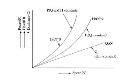
- We know that
 This means that the curve P versus N is Cubic curve shown in figure
 - We know that
 for a given curve. Hence the curve Q versus N is a straight line as shown in figure
Operating characteristic curves
- If the speed is kept constant the variation of manometric head, power and efficiency with respect to discharge give the operating characteristics of the pump.
|

- Figure shows the operating characteristic curves of a pump.
- The input power curve for pump shall not pass through the origin.
- It will be slightly away from the origin on the y axis as even at zero discharge some power is needed to overcome mechanical losses.
- The head curve will have maximum value of head when discharge is zero.
- The output power curve will start from origin as at Q equals to zero output power
 will be zero.
 - The efficiency curve will start from origin as at Q equals to zero

Constant efficiency curves
- For obtaining constant efficiency curves for a pump, the head versus discharge curves and efficiency vs discharge curves for different speed are used.
|

- Figure shows the head vs discharge curve for different speeds.
- The efficiency vs discharge curves for the different speeds are as shown in figure b.
- By combining these curves
 curve
curve  constant efficiency curves are obtained as shown in figure a.
 - For plotting the constant efficiency curves horizontal lines representing constant efficiencies are drawn on the
 .
. - The points at which these lines cut the efficiency curve at various speeds, are transformed to the corresponding H~Q curves.
- The points having the same efficiency are then joined by smooth curves.
- The smooth curve represents the iso efficiency curves
Numericals
- A centrifugal pump is to discharge
 at a speed of 1450 rpm against a head of 25m. The impeller diameter is 250 mm, its width at outlet is 50mm and manometric efficiency is 75%. Determine the vane angle at the outer periphery of the impeller.
Solution
Given
Discharge, Q=
Speed , N=1450 rpm
Head  =25m
=25m
Diameter at outlet  =250mm=0.25m
Width at outlet  =50mm=0.05m
Manometric efficiency 
|
Tangential velocity of impeller at outlet

Discharge is given by 
Using equation 

From outlet velocity triangle we have


2. A centrifugal pump delivers water against a net head of 14.5 metres and a design speed of 1000 rpm. The vanes are curved back to an angle of 30 degree with the periphery. The impeller diameter is 300 mm and outlet width is 50mm. Determine the discharge of the pump if manometric efficiency is 95%.
Given
Net head 
Speed N=1000 r.p.m
Vane angle at outlet 
Impeller diameter 
Outlet width 
|

Manometric efficiency 
Tangential velocity of impeller at outlet

Now using equation 
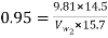
 = 9.54m/s
from outlet velocity triangle


3. A centrifugal pump having outer diameter equal to two times the inner diameter and running at 1000 rpm works against a total head of 40m. The velocity of flow through the impeller is constant and equal to 2.5m/s .The vanes are set back at an angle of 400 at outlet . If the outer diameter of the impeller is 500mm and width at outlet is 50mm Determine
- Vane angle at inlet
- Work done by impeller on water per second
- Efficiency
Given
Speed N=1000rpm
Head 
Velocity of flow 
Vane angle at outlet 
Outer diameter of impeller 
Inner diameter of impeller 
Width at outlet 
|

Tangential velocity of impeller at inlet and outlet are
And 
Discharge is given by 
- Vane angle at inlet
From inlet velocity triangle 

from outlet velocity triangle we have


2. Work done by impeller on water per second is given by equation as

=119227.9Nm/s
3. Manometric efficiency

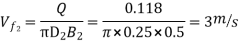
4. The outer diameter of an impeller of a centrifugal pump is 400mm and outlet width is 50mm. The pump is running at 800 rpm and is working against a total head of 15m. The vanes angle at outlet is 400 and manometric efficiency is 75%. Determine
- Velocity of flow at outlet
- Velocity of water leaving the vane
- Angle made by the absolute velocity at outlet with the direction of motion at outlet and
- Discharge
Given
Outer diameter 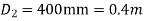
Width at outlet 
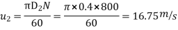
Speed N=800rpm
Head 
Vane angle at outlet 
Manometric efficiency 
|

Tangential velocity of impeller at outlet


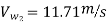
From the outlet velocity triangle


Velocity of water leaving the vane


Angle made by absolute velocity at outlet


Discharge through pump is given by


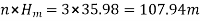
5. A three stage centrifugal pump has impellers 40cm in diameter and 2 cm wide at outlet. The vanes are curved back at the outlet at 450 and reduce the circumferential area by 10%. The manometric efficiency is 90% and the overall efficiency is 80% Determine the head generated by the pump when running at 1000 rpm delivering 50 litres per second. What should be the shaft horse power ?
Given
Number of stages n=3
Diameter of impeller at outlet 
Width at outlet 
Vane angle at outlet 
Reduction in area at outlet =10%= 0.1
Area of flow at outlet =
Manometric efficiency 
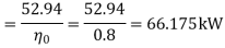
Overall efficiency 
Speed N=1000rpm
Discharge Q = 50litres/s = 0.05 
Velocity of flow at outlet 
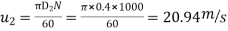
Tangential velocity of impeller at outlet,
from velocity triangle at outlet,


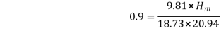
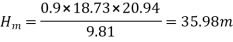
Total heat generated by pump =
Power output of the pump= 


Reference:
1. Hydraulics & Fluid mechanics – Modi & Seth
2. Fluid mechanics & hydraulic machines. – R.K. Bansal


