Unit 2
Reaction Turbines
Francis turbine
- The purpose of the casing is to provide an even distribution of water around the circumference of the turbine runner, maintaining an approximately constant velocity for the water so distributed.
- The casing is made of a cast steel, plate steel, concrete and steel depending upon the pressure to which it is subjected.
- From the scroll casing the water passes through a speed ring held together by series of fixed vanes called stray vanes.
- The speed wing has two functions to perform.
- It directs the water from the scroll casing to the guide vanes.
- Further it resists the load imposed upon it by internal pressure of water and the weight of the turbine and the electrical generator and transmits the same to the foundation.
- From the speed ring the water passes through a series of guide vanes provided all around the periphery of the turbine runner.
- The function of guide vanes is to regulate the quantity of water supply to the runner and to direct water onto the runner at an angle approximate to the design.
- Guide vanes can turn about their stems. So as to alter the width of the passage between them.
- The runner of Francis turbine consists of series of curved veins evenly arranged around the circumference in the annular space between two plates.
- The vanes are so shaped that water enters the runner at the outer periphery and leaves it axially at the lower periphery.
- The change in the direction of flow of water from radial to axial as it passes through the runner, produces a circumferential force on the runner which makes the runner to rotate and thus contribute to useful output of the runner.
- The torque produced by the runner is transmitted to the generator through the shaft which is usually connected to the generator shaft by a bolted flange connection.
- The water after passing through runner flows to the tail race through to a draft tube.
Kaplan Turbines
- It is an axial flow turbine, which is suitable for relative low heads and hence requires a large quantity of water to develop large amount of power.
- As shown in figure the main component of Kaplan turbine are scroll casing, stay ring arrangement of guide vanes and the draught tube.
- Between guide vanes and the runner the water in Kaplan turbine turns through right angle into axial direction and then passes through the runner.
- The runner of a Kaplan turbine has 4 or 6 blades.
|

- The blades attached to a hub for boss are so shaped that water flows axially to the runner.
- Ordinarily the runner blades of propeller turbines are fixed, but the Kaplan turbine runner blades can be turned about their own axis, so that their angle of inclination maybe adjust while the turbine is in motion.
- The adjustment of the runner blades is usually carried out automatically by means of servomotor operating inside the hollow coupling of turbine and generator shaft.
- When the vanes are fixed to the hub and are not adjustable, the turbine is known as propeller turbine.
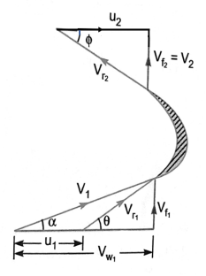
- Velocity triangles for reaction turbines are as shown in figure.
|

- From the velocity triangles, the work done by the water on the runners, horsepower and efficiency of the turbine can be obtained.
The work done per second on the runner by water is given by equation


=  Q[
Q[
Where
 Velocity of whirl at inlet and outlet
 = Tangential velocity of wheel of inlet and outlet
The work done per second per unit weight of water per second
=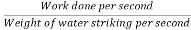
= 
=
Hydraulic efficiency = 
=
Where
RP = Runner power
WP = Water power
If discharge is radial 
 = =
= =
Efficiencies of a Turbines: The following are the important efficiencies of a turbine.
a) Hydraulic efficiencies, ηh
b) Mechanical efficiencies, ηm
c) Volumetric efficiencies, ηv and
d) Overall efficiencies, ηo
a) Hydraulic efficiency It is defined as the ratio of power given by water to the runnerof a turbine (runner is a rotating part of the turbine and on the runner vanesare fixed) to the power supplied by the water at the inlets of the turbine. The power at inlet of the turbine is more and this power goes on decreasing as the water flows over the vanes of the turbine due to hydraulic losses as the vanes are not smooth. Hence the power delivered to the runner of the turbine will be less than the power available at the inlets of the turbine. Thus mathematically, the hydraulic efficiency of the turbine is written as.
ηh = 
above R.P. = Power delievered to runner i.e., runner power
 ... for Pelton Turbine
 ... for a radial Flow Turbine
W.P. = Power supplied at inlet of turbine and also called water power
= 
Where, W = Weight of water striking the vanes of the turbine per second
= ρg × Q in which Q = Volume of water/s


u = Tangential velocity of vane
u1 = Tangential velocity of vane at inlet for radial vane
u2 = Tangential velocity of vane at inlet for radial vane
H = Net head on the turbine.
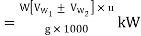
Power supplied at the inlet of turbine in S.I. units is known as water power. It is given by
W.P. =  .......................(A)
For water ρ = 1000 kg/m3
W.P. =  = g× Q× HkW .......................(B)
The relation (B) is only used when the flowing fluid is water. If the flowing fluid is other than the water, then relation (A) is used.
b) Mechanical Efficiency (ηm) The power delivered by water to the runner of a turbine is transmitted to the shaft of the turbine. Due to mechanical losses, the power available at the shaft of the turbine is less than the power delivered to the runner of a turbine. The ratio of the power available at the shaft of the turbine (known as S.P. or B.P.) to the power delivered to the runner is defined as mechanical efficiency. Hence, mathematically, it is written as
ηm = 
c) Volumetric Efficiency (ηv) The volume of the water striking the runner of a turbine is slightly less than the volume of the water supplied to the turbine. Some of the volume of the water is discharged to the tail race without striking the runner to the volume of water supplied to the turbine is defined as volumetric efficiency. It is written as
ηv = 
Overall Efficiency (ηo) It is defined as the ratio of power available at the shaft of the turbine to the power supplied by the water at the inlet of the turbine. It is written as:
ηo = 
= S.P./W.P.
- Degree of reaction is defined as the ratio of pressure drop in the runner to hydraulic work done on the runner.
- It is denoted by

- Thus if
 are the pressure at the inlet and outlet of the runner then,
If 
 =
=
- The draft tube is pipe of gradually increasing area which connects the outlet of the runner to the tail race.
- It is used for discharging water from the exit of the turbine to the tail race.
- Draft has following function to perform
It permits negative head to be established at the outlet of the runner and thereby increase the net head on the turbine.
The turbine may be placed above the tail race without any loss of net head and hence turbine may be inspected properly.
It converts a large portion of kinetic energy (  at the outlet of turbine into useful pressure energy.
- Hence by using draft tube the net head on the turbine increases.
- The turbine develops more power and also the efficiency of turbine increases.
Types of draft tubes
The following are the important types of draft tubes which are commonly used
1) Conical draft tube
- In this type of draft tube, the flow path is straight and divergent. This draft tube is fabricated with mild steel plates.
- It is tapered in shape and the outlet diameter is larger than inlet diameter of this draft tube.
- The tapered angle of draft tube should not be too large as it will cause the separation of flow from the wall of draft tube.
- This angle should not be too small also as it will require a longer draft tube which causes a significant loss of kinetic energy. So the taper angle is always nearly 10 degrees.
2) Simple elbow tubes
- In Simple Elbow draft tube, the tube is of elbow shaped. It is mainly used in Kaplan turbine.
- In this type of draft tube, the cross section area remains same throughout the length of draft tube.
- The inlet and outlet of the draft tube is circular shaped.
- This draft tube is generally used at places of low head and the turbine is to be placed close to the tail race.
- It helps to cut down the cost of excavation and the exit diameter should be as large as possible to recover kinetic energy at outlet of runner.
|

3) Moody spreading tubes
- In this type of draft tube, the outlet of the daft tube is divided into two parts.
- It is similar to conical draft tube and is provided with the central core part which divide the outlet into two parts.
- There is one inlet and two outlets of this draft tube.
- This type of draft tube is mainly used to reduce the swirling action of water.
- It is used in vertical shaft turbine.
- Efficiency of this type of draft tube is nearly 88 percent.
4) Elbow draft tubes with circular inlet and rectangular outlet
- Elbow draft tube with varying cross section is an improvement of simple elbow draft.
- In this type of draft tube, the inlet is circular and the outlet is of rectangular shape.
- The horizontal part of the draft tube is generally inclined upwards to prevent entry of the air from the exit end.
- The cross-section area of this type of draft tube changes from inlet to outlet. Outlet of this draft tube is always below the tail race.
- It is generally used in Kaplan Turbine and efficiency of this type of draft tube is about 70 percent.
Draft tube theory: -
Consider a conical draft tube as shown in figure.
|

 Vertical height of draft tube above the tail race
y = distance of bottom of draft tube from tail race
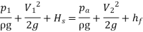
Applying Bernoulli's equation to inlet (section 1-1) and outlet (section 2-2) of the draft tube and taking section 2-2 as the datum line we get

 loss of energy between section 1-1 and 2-2.
But,  atmospheric pressure head + y
= 
Substituting this value of  in equation (i) we get
 =
=
 -
-
=
In above equation,  is less than atmospheric pressure.
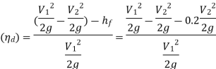
Efficiency of draft tube
The efficiency of a draft tube is defined as the ratio of actual conversion of kinetic head into pressure head in the draft tube to the kinetic head at the inlet of the draft tube.
Mathematically,
 =
= 
 Velocity of water at inlet of draft tube
 Velocity of water at outlet of draft tube and,
 Loss of head in the draft tube
Theoretical conversion of kinetic head into pressure head in draft tube = 
Actual conversion of kinetic head into pressure head=
= 
- When the pressure in any part of the flow passage reaches the vapour pressure of the flowing liquid, it starts vaporizing and small bubbles of vapour form in large numbers.
- These bubbles are carried along by the flow and on reaching the high pressure zones these bubbles suddenly collapse as the vapour condenses to liquid again.
- Due to sudden collapsing of the bubbles cavities are formed.
- The surrounding liquid rushes in to them.
- The liquid moving from all directions collides at the centre of the cavity, thus giving rise to very high local pressure.
- Any solid surface in the vicinity is also subjected these intense pressure.
- The alternate formation and collapse of vapour bubbles may cause serve damage to the surface which ultimately fails by fatigue and the surface becomes badly scored and pitted.
- This phenomenon is known as cavitation.
Precautions against cavitation
The following precautions should be taken against cavitation
- The pressure of the flowing liquid in any part of the hydraulic system should not be allowed to fall below its vapour pressure. If the flowing liquid is water, then the absolute pressure head should not be below 2.5 m of water.
- The special materials or coatings such as aluminium bronze and stainless steel which are cavitation resistant materials should be used.
- Geometric Similarity:
For geometric similarity to exist between the model and the prototype, the ratios of corresponding lengths in the model and the prototype must be same and the included angles between the corresponding sides must be the same.
Models which are not geometrically similar are known as geometrically distorted model.
Lm = length of model
Hm = height of model
Dm = diameter of model
Am = area of model
Vm = volume of model
And LP, BP, HP, DP, AP and VP = corresponding values of prototype.
Then, for geometric similarity, we must have the relation:
Where Lr is called the scale ratio or the scale factor:


- Kinematic similarity:
Kinematic similarity is the similarity of motion.
If at the corresponding points in the model and in the prototype, the velocity or acceleration ratio are same & velocity or acceleration vectors point in the same direction, the two flows are said to be kinematically similar.
(V1)m = velocity of fluid at point 1 in the model.
(V2)m = velocity of fluid at point 2 in the model,
(a1)m = acceleration of fluid at point 1 in the model
(a2)m = acceleration of fluid at point 2 in the model
And (V1)P, (V2)P, (a1)P (a2)P = corresponding values at the corresponding points of fluid, velocity and acceleration in the prototype.
Then, for kinematic similarity, we must have
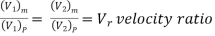
Similarly, 
The direction of the velocities in the model and prototype should be same.
The geometric similarity is a pre-requisite for kinematic similarity.
Dynamic Similarity
Dynamic similarity is the similarity of forces. The flows in the model and in prototype are dynamically similar if at all the corresponding points, identical types of forces are parallel and bear the same ratio.
In dynamic similarity, the force polygons of the two flows can be superimposed by change in force scale.
(Fi)m = inertia force at a point in the model,
(Fv)m = viscous force at the point in the model,
(Fg)m = gravity force at the point in the model
And (Fi)P, (Fv)P, (Fg)P = corresponding values of forces at the corresponding points in prototype.
Then, for dynamic similarity we have
The direction of the corresponding forces at the corresponding points in the model and prototype should also be same.
- In order to have an idea about the performance of the actual turbine in advance a small scale model of the turbine which is geometrically similar to the actual turbine is first prepared.
- The model turbine is then tested under a known head, and flow rate and its output as well as the efficiency are determined.
- From these test results it will be possible to predict the performance of the actual turbine on the basis of the test results.
- If the design is to be modified it maybe so done in the model turbine without incurring much expenditure.
- Thus model testing of turbines assists in obtaining a perfect design for the actual turbines, as well as in the development of the new types of turbines with higher specific speed and better efficiency.
- The various variables involved in this case are discharge Q, head H, speed N, runner diameter D, output power P, mass density
 and viscosity
  .
. - These variables may be grouped into following dimensions parameter (
 discharge number,
  head number and
  power number and
  Reynolds number.
 - For complete similarity to exist between the model and prototype turbines the following conditions may be required to be satisfied
|

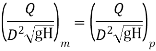
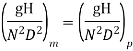

- Where the subscripts m and p refer to model and prototype turbines respectively.
- By determining the values P,H,N and D from the model test the values of the above noted parameters are determined which will be same for both model and the prototype turbines.
- For the prototype turbine since its diameter D and head H are known, its speed N, power P and discharge Q can thus be calculated with the help of the known values of these parameters.
- For similarity between the model and the prototype turbines the values of the various unit quantities must be equal for both.
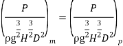
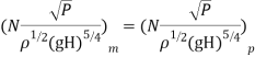
- The above conditions for establishing the similarity between the model and the prototype turbines are based on the assumption that the efficiency of the model is equal to that of the prototype.
- However, the efficiencies of the model and the prototype turbines are not equal.
- The modified expressions for the similarity conditions may be obtained as indicated below.
- If
 are the overall efficiencies of the model and prototype turbines respectively then


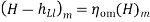

- By considering these values of the head in place of H the following expression are obtained
|


- It is defined as the speed of turbine which is identical in shape, geometrical dimensions, blade angles, gate opening etc. with actual turbine but of such size that it will develop unit power when working under until head.
- It is denoted by symbol

Overall efficiency  =
=
 =
= 
Where H=head under which the turbine is working
Q=discharge through turbines
P=power developed for shaft power

P Q× H
Q× H
As  and
and  are constant …..(ii)
D= diameter of actual turbine
N=speed of actual turbine
u=tangential velocity of the turbine
 Specific speed of turbine
V=absolute velocity of water
But. u  V where V
 √H
√H
u √H (iii)
But. u=
u DN….(iv)
From equation (iii) and (iv)
√H.  DN
DN
Or D

Discharge Q= A×V
A  B×D
B×D


V √H
√H


Put the value of Q in equation (ii)
 ×H
×H


P=
where K=constant of proportionality
If P=1 and H=1 Speed N=Specific speed
Put these values in above equation


Or 

Significance:-
- Specific speed play an important role for selecting the type of the turbine.
- Also performance of a turbine can be predicted by knowing the specific speed of the turbine.
- Important parameters which are varied during a test on a turbine
1) Speed (N)
2) Head (H)
3) Discharge (Q)
4) Power (P)
5) Overall efficiency (
6) Gate opening
- Out of the above 6 parameters, three parameters namely speed head and discharge are independent parameters.
- Out of the three independent parameters (N,H,Q) one of the parameter is kept constant and the variation of the other four parameters with respect to anyone of the remaining two independent variables are plotted and various are obtained.
- These are called characteristic curves.
- The following are the important characteristic curves of a turbine.
Constant head curves
- These curves are obtained by keeping head constant and a constant gate opening on the turbine.
- The speed of the turbine is varied by changing load on the turbine.
- For each value of speed, the corresponding values of the power(P), discharge(Q) are obtained.
|


For reaction turbines
- Then the overall.
 or each value of the speed is calculated.
 - From these reading the values of unit speed
 ,unit power
  a determined.
 - Taking
 as abscissa, the values of
  are plotted as shown in figure by changing the gate opening, the values of
  are determined and taking
  as abscissa.
 - Figure a shows the main characteristic curves for Pelton wheel and figure b shows the main characteristic curves for reaction turbines.
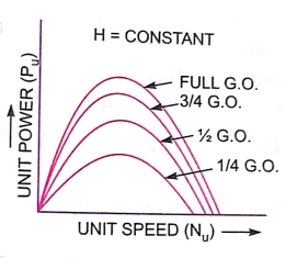
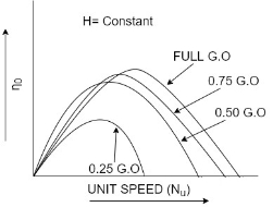
Operating characteristic curves for constant speed curves
- Operating characteristic curves are plotted when speed on the turbine is constant.
- In case of turbines, the head is generally constant.
|

- For operating characteristics N and H are constant and hence the variation of power and efficiency with respect to discharge Q are plotted.
- The power curve for turbines shall not pass through the origin because certain amount of discharge is needed to produce power to overcome initial friction.
- Hence the power and efficiency curves will be slightly away from the origin on the x-axis, as to overcome initial friction certain amount of discharge will be required.
- Shows the variation of power and efficiency with respect to discharge.
Constant efficiency curves or Muschel curves or iso-efficiency curves
- These curves are obtained from speed versus efficiency and speed versus discharge curves for different gate opening.
- For a given efficiency from the
 curves, there are two speeds.
 - From
 curves, corresponding to two values of speeds there are two values of discharge.
|

- Hence for a given efficiency there are two values of discharge for the particular gate opening.
- This means for a given efficiency there are two values of speeds and two values of discharge for a given gate opening.
- If the efficiency is maximum there is only one value.
- These two values of speed and two values of discharge corresponding to particular gate opening are plotted as shown in figure.
- The procedure is repeated for different gate opening and the curves Q vs N are plotted.
- The points having the same efficiency are called iso- efficiency curves.
- These curves are helpful for determining the zone of constant efficiency and for predicting the performance of the turbine at various efficiencies.
- For plotting the iso-efficiency curves horizontal lines representing the same efficiency are drawn on the
 speed curves.
 - The points at which these lines cut the efficiency curves at various gate openings are transferred to the corresponding Q~ speed curves.
- The points having the same efficiency are less then joined by a smooth curve.
- These smooth curves represent the ISO efficiency curve.
Following factors are considered for selecting a particular turbine at place
1) Head: - The net head under which the turbine is working plays an important role for selecting turbine.
The type of turbine for different heads
Net head in m | Types of turbine |
300m or more | Pelton turbine |
150m to 300m | Pelton or Francis |
50m to 150m | Francis turbine |
Less than 50 m | Kaplan or propeller |
2) Specific speed:- The specific speed is also an important factor for deciding the type of turbine to be installed at a place.
Specific speeds | Types of turbines |
85 to 30 | Pelton wheel with single jet |
31 to 50 | Pelton wheel with double jet |
51 to 225 | Francis |
256 to 860 | Kaplan or propeller |
3) Part load operation :-
- The turbines are not working always at full load.
- There is considerable load variation.
- At full load all the turbines are having approximately equal efficiency but at part load the efficiency of Kaplan and Pelton turbines are approximately equal to the efficiency of full load.
- But the efficiency of Francis and propeller turbines are 60% of the efficiency at full load.
- Hence the performance of Kaplan and Pelton turbines is better than Francis and propeller turbine.
4) overall cost of installation and cavitation characteristics :-
- The overall cost of installation of a turbine which consists of initial cost and running cost should be considered for selecting a type of turbine at site.
- Also the cavitation characteristics for installation of reaction turbine should also be considered.
Numericals:
- Reaction turbine works at 450 r.p.m. under a head of 120 metres. Its diameter at inlet is 120 cm and the flow area is 0.4
 The angles made by absolute and relative velocity at inlet are 20° and 60° respectively with the tangential velocity. Assume whirl at outlet to be zero. Determine
a) Volume flow rate
b) The power developed and
c) Hydraulic efficiency
Sol.
Given,
Speed of turbine, N=450 r.p.m
Head, H= 120m
Diameter at inlet, 
Flow area = 
Angle made by absolute velocity at inlet.  = 20°
= 20°
Angle made by the relative velocity at inlet Ѳ =60°
Whirl at outlet 
|
Tangential velocity of turbine at inlet

From inlet velocity triangle


Also, tan Ѳ =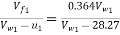
 60
60

a) Volume flow rate 

b) Work done per sec on the turbine =
=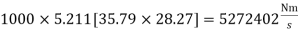
Power developed in KW= Work done per second/1000=5272402/1000=5272.402KW
c) Hydraulic Efficiency
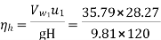
=0.8595 = 85.95%
2. An inward flow reaction turbine has external and internal diameters as 1.0 m and 0.6 m respectively. The hydraulic efficiency of the turbine is 90% when the head on the turbine is 36m. The velocity of flow at inlet is 2.5 m/s and discharge at outlet is radial. If the vane angle at outlet is 15 degree and width of the wheel is 100 mm at inlet and outlet, determine
I) The guide blade angle
II) Speed of the turbine
III) Vane angle of the runner at inlet
IV) Volume flow rate of turbine and
V) Power developed
Sol.
Given
External diameter=
Internal Diameter 
Hydraulic Efficiency ηh=90%=0.90
Head H=36m
Velocity of flow at outlet 
Discharge in radial 
Vane angle at outlet 
Width of wheel 
|

For hydraulic efficiency 

 ………………………….(1)
From outlet velocity triangle 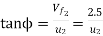
 m/s
m/s


Substituting this value of  in equation (1)
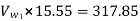


1) Guide blade angle (
From inlet velocity triangle 
(ii)Speed of the turbine N=296.98rpm
(iii)Angle of runner at inlet t

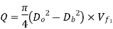
 Volume flow rate of turbine =
(v) Power developed (in KW)= Work done per second /1000 = 
= =149.76kW
3. An outward flow reaction turbine has internal and external diameter of the runner as 0.6 m and 1.2 m respectively. The guide blade angle is 15 degree and velocity of flow through the runner is constant and equal to 4 m/s. if the speed of the turbine is 200 r.p.m head on the turbine is 10m and discharge at outlet is radial, determine
(i) The runner vanes angles at inlet and outlet
(ii) Work done by the water on the runner per second per unit weight of water striking per second
(iii) Hydraulic efficiency and
(iv) The degree of reaction
Sol.
Internal Diameter 
External Diameter 
Guide blade angle 
Velocity of flow 
Speed N=200rpm
Head H=10m
Discharge at outlet = Radial
|

Tangential velocity of runner at inlet and outlet are:


From the inlet velocity triangle 

- Runner Vane angles at inlet and outlet are


θ = tan-1 .4627=24.83
From outlet velocity triangle 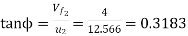
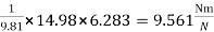
2. Work done by water per second per unit weight of water striking per second
=
=
3. Hydraulic efficiency


4. In this question the velocity of flow is constant through the runner  the degree of reaction is given by equation
R=1-
Here,

Substituting the value of  we get,
R=
4. Kaplan turbine working under a height of 20m develops 11772 kW shaft power. The outer diameter of the runner is 3.5 m and inner diameter is 1.75 m. The guide blade angles at the extreme edge of the runner is 35 degree. The hydraulic and overall efficiencies of the turbines are 88% and 84% respectively. If the velocity of wheel is zero at outlet, determine
(i)Runner vane angles at inlet and outlet at the extreme edge of the runner and
(ii) Speed of the turbine
Sol.
Given
Head, H=20m
Shaft power, S.P.=11772Kw
Outlet diameter of runner, 
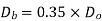
Hub diameter, 
Guide blade angle, 
Hydraulic efficiency, 
Overall efficiency, 
Velocity of whirl at outlet=0
|

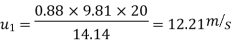
Using the relation, 
Where, W.P. =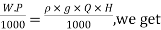

0.84 


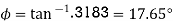
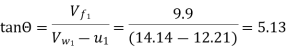
From the velocity triangle, tan 

Using the relation for hydraulic efficiency,

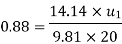
(i) Runner vane angles at inlet and outlet at the extreme edge of the runner are given as

For Kaplan turbine,

From outlet velocity triangle, 

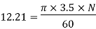
(ii) Speed of turbine is given by 

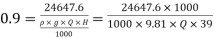
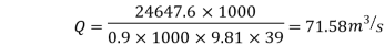
5. A Kaplan turbine develops 2464 7.6 kW power at an average height of 39 meters. Assuming a speed ratio of 2, flow ratio of 0.6, diameter of the boss equal to 0.35 times the diameter of the runner and an overall efficiency of 90%, calculate the diameter, speed and specific speed of the turbine.
Sol. Given,
Shaft power, S.P.=24647.6BkW
Head, H=39m
Speed ratio,  0
0

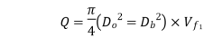
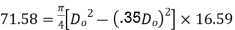
Flow ratio, 

Diameter of boss =0.35 Diameter of runner
Overall efficiency , 
Using the relation, 


(ii)Speed of the turbine is given by 


(iii)Specific speed is given by  , where P=Shaft power in Kw

6. A conical draft tube having inlet and outlet diameters 1m and 1.5 m discharges water at outlet with a velocity of 2.5m/s. The total length of the draught tube is 6m and 1.20m of the length of draft tube is immersed in water. If the atmospheric pressure head is 10.3 m of water and loss of head due to friction in the draft tube is equal to 0.2 × velocity head at outlet of the tube, find:
(i)Pressure head at inlet and
(ii)Efficiency of the draft tube
Sol. Given,
Diameter of inlet,  1.0 m
1.0 m
Diameter at outlet,  1.5 m
1.5 m
Velocity at outlet, 
Total length of tube, 
Length of tube in water, y=1.20m
 =6.0 - 1.20 = 4.80 m
Atmospheric pressure head, 
Loss of head due to friction,  0.2
0.2 Velocity head at outlet
= 
Discharge through tube, 
Velocity at inlet, 
(i)Pressure head at inlet 


=4.27 m (abs.)
(ii)Efficiency of draft tube
=
|

7.A turbine is to operate under a head of 2.5 m at 200 r.p.m. The discharge is 9 cumec. If the efficiency is 90%, determine the performance of the turbine under a head of 20 meters.
Sol.
Given,
Head of turbine,  = 25m
= 25m
Speed,  =200 r.p.m
Discharge, 
Overall efficiency, 
Performance of the turbine under a head,  , means to find the speed, discharge and power developed by the turbine when working under the head of 20 m.
Let for the head ,  , Speed=
 , discharge=
 and power =
Using the relation, 

 1986.5 kW
Using the relation , 

Also , 

And, 

Reference:
1. Fluid Mechanics & Hydraulics Machines- R.K. Bansal
2. Hydraulics & Fluid Mechanics – Modi & Seth


