Unit 1
Introduction: Impulse of Jet and Impulse Turbines
1.Based on energy transfer
- Energy is given by fluid to the rotor – Power generating Turbo machine. E.g. Turbines
- Energy given by the rotor to the fluid - Power Absorbing Turbo machine. E.g. Pumps, blowers and compressors
2.Based on fluid flowing in turbo machine
- Water
- Air
- Steam
- Hot gases
- Liquids like petrol etc.
3.Based on direction of flow through the impeller or vanes or blades, with reference to the axis of shaft rotation
- Axial flow – Axial pump, compressor or turbine.
- Mixed flow - Mixed flow pump, Francis turbine
- Radial flow - Centrifugal pump and compressor
- Tangential flow - Pelton water turbine
4.Based on condition of fluid in turbo machine
- Impulse type (constant pressure) E.g. Pelton water turbine
- Reaction type (variable pressure) E.g. Francis reaction turbines
5.Based on position of rotating shaft
- Horizontal shaft – Steam turbines
- Vertical shaft - Kaplan water turbines
- Inclined shaft - Modern bulb micro
It is based on law of conservation of momentum or on the momentum principle, which states that the net force acting on a fluid mass is equal to the change in momentum of flow per unit time in that direction.
The force acting on a fluid mass m is given by the Newton’s second law of motion.
F = m x a
Where a is the acceleration acting in the same direction as force F
But a = 
F = m x 
=  m is constant can be taken inside the differential
Above equation is known as the momentum principle.
It can be written as F dt = d(mv)
Which is known as the momentum equation & states that the impulse of force F acting on a fluid of mass m in a short interval of time dt is equal to the change of momentum d(mv) in the direction of force.
Applications of the Impulse - Momentum Equation
1.For any problems involving F, v, t:
The impulse Momentum equation may be used for any problems involving the variables force F , velocity v, and time t. The IM equation is not directly helpful for determining acceleration, a, or displacement, s.
2. Helpful for impulsive forces:
The IM equation is most helpful for problems involving impulsive forces. Impulsive forces are relatively large forces that act over relatively short periods of time for example during impact. If one knows the velocities, and hence momenta, of a particle before and after the action of an impulse, then one can easily determine the impulse. If the time of impulse is known, then one can calculate the average force that act during the impulse.
3.For problems involving graph of F vs. t :
Some problems give a graph of Force vs. time. The area under this curve is impulse.
- An outward flow radial machine.
- Fluid approaches along the suction pipe, is picked up and operated upon by the rotor and is discharged into the casing at a higher level of energy.
- The rotor has imparted both a velocity and a radial position change to the fluid, which together result in momentum changes and resultant forces on the rotor.
- Since momentum changes in the tangential direction give rise to a torque and thus to work.
- Moment of momentum equations for elemental areas of flow at the points of entry and exit will be written down.
- The normal fluid velocities are Vn1 andVn2.
- If elemental areas of flow da1 and da2 are examined.
- The moments of momentum entering the rotor at 1 and 2 are given by
dM1 = ( Vn1 da1) Vu1 R1
dM2 = ( Vn2 da2) Vu2 R2
Thus the total moments of momentum are
M1 = 
M2 = 
The fluid torque is the net effect given by
T = M1 + M2
= ………………. 1
It is assumed that Vu R is a constant across each surface and it is noted that  is the mass flow rate m.
Then equation (1) becomes
T = m(Vu1 R1 - Vu2 R2) ………………………………………….. 2
The rate of doing work is  T and since
  R is the rotor peripheral velocity u
at radius R, equation (2) can be transformed to give work done per unit
mass:
g H = u1 Vu1 - u2 Vu2
This is one form of the Euler equation.
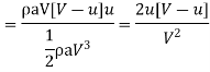
Force exerted by the jet on a stationary vertical plate
Consider a jet of water coming out from the nozzle, strikes a flat vertical plate as shown in Fig
|

V = velocity of the jet
d = diameter of the jet
a = area of the cross section of the jet
= 
The jet after striking the plate, will move along the plate.
But the plate is at right angles to the jet.
Hence the jet after striking will get deflected through 90°.
Hence the component of the velocity of jet, in the direction of jet, after striking will be zero.
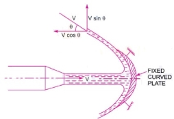
The force exerted by the jet on the plate in the direction of jet,
 =rate of change of momentum in the direction of force
= 

= 
=
= (Mass/sec) x (velocity of Jet before striking - velocity of Jet after striking)
= 
= 
Force exerted by Jet on stationary inclined flat plate
Let Jet of water, coming out from the nozzle, strikes and inclined flat plate as shown in Fig.
|

V = Velocity of jet in the direction of 
 = Angle between the jet and plate
a = area of cross section of the jet
Then mass of water per second striking the plate = 
If the plate is smooth and if it is assumed that there is no loss of energy due to impact of the jet, then Jet will move over the plate after striking with a velocity equal to initial velocity.
The force exerted by the jet on the plate in the direction normal to the plate.
 = mass of Jet striking per second × [ initial velocity of Jet before striking in the direction of
  - final velocity of Jet after striking in the direction of
  ]
]
=  θ
θ
 = component of
  perpendicular to flow
=  θ) =
θ) =  θ =
θ =  θ
θ  θ
θ
= 
 =component of
  perpendicular to flow.
=  θ) =
θ) =  θ =
θ =  θ
θ  θ
θ
Force exerted on moving flat plate
Force on flat vertical plate moving in the direction of jet
Fig. shows a jet of water striking a flat vertical plate moving with a uniform velocity away from the jet.
|

Let , V =velocity of jet
a = area of cross section of jet
u = velocity of the flat plate
In this case, Jet does not strike the plate with a velocity  but it strikes with a reflective velocity which is equal to the absolute velocity of jet of water minus the velocity of the plate.
Therefore, relative velocity of the jet with respect to plate= V- u
Mass of water striking the plate per sec
=  ×area of jet × velocity with which Jet strikes the plate
=  a[V-u]
Force exerted by the jet on the moving plate in the direction of the jet,
 =mass of water striking per ×[initial velocity-final velocity]
= a[V-u] [(V-u)-0]
= 
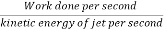
Work done per second by the jet on the plate =
=
Force on the inclined plate moving in the direction of the jet
Let a jet of water strikes on the inclined plate, which is moving with uniform velocity in the direction of the jet as shown in fig.
|

Let V=Absolute velocity of jet of water
u = Velocity of the plate in the direction of jet
a = Cross sectional are of jet
 Angle between jet and plate
Relative velocity of jet and water=V- u.
Therefore, Mass of water striking per second=  a[V-u]
If the plate is smooth and loss of energy due to impact of the jet is assumed zero, the jet of water on the plate with a velocity equal [V- u]
The force exerted by the jet water on the plate in the direction normal to the plate is given as
 Mass striking per second
  [Initial velocity - Final velocity]
=  a(V-u)[(V-u)sin θ]
= sin θ
sin θ
This normal force  is resolved into two components namely
  in the direction of jet and perpendicular to the direction of the jet respectively.

 sin θ =
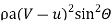

 cos θ =
 (V-u)
(V-u)
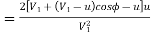
Work done per second by the jet on the plate
=
=
=
Force exerted on hinged plate
Consider a jet of water striking a vertical plate at the centre which is hinged at O.
Due to the force exerted by the jet on the plate, the plate swing through some angle about the hinge as shown in fig.
|

Let x= distance of the centre of Jet from hinge O
Θ= Angle of Swing about hinge
W=weight of plate acting at C.G. of the plate
The dotted line shows the position of the plate, before the jet strikes the plate. The point A on the plate will be of A' after the jet strikes the plate.
The distance OA= OA'=x
Let the weight of the plate is acting at A'. When the plate is in equilibrium after the jet strikes the plate. The moment of all the forces about the hinge must be zero.
Two force are acting on the plate
1.Force due to Jet of water, normal to the plate

Where  = angle between jet and plate
= (90- )
)
2.Weight of the plate, W
Moment of force  about hinge


= 
Moment of weight W About hinge
= W × OA’ sin θ
= W×  θ
θ
For equilibrium of the plate


Force exerted on curved vanes
Force exerted by a jet on stationary curved plate
A) Jet strikes the curved plate at the centre.
Let a Jet of water strikes a fixed curved plate at the centre as shown in Fig.
|
The Jet after striking the plate, comes out with the same velocity. If the plate is smooth and there is no loss of energy due to impact of the jet, in the tangential direction of the curved plate.
The velocity at outlet of the plate can be resolved into two components, one in the direction of jet and other perpendicular to the direction of the jet.
Component of velocity in the direction of jet
=  θ
θ
Component of velocity perpendicular to the jet
=  θ
θ
Force exerted by the jet in the direction of jet,
 =
= × [
× [
 = Initial Velocity in the direction of jet=
 = Final velocity in the direction of jet=
  θ
θ
 =
= θ
θ =
=  θ
θ
=  θ
θ

Similarly,
 =initial velocity in the direction of
 =final velocity in the direction of
  θ
θ
 θ] =
θ] =  θ
θ
Negative sign means that forces acting in the downward direction. In this case the angle of deflection of the jet = (180°- θ)
B) Jet strikes the curved plate at one end tangentially when the plate is symmetrical.
Let the jet strikes the curved fixed plate at one end tangentially as shown in fig.
|

Let the curved plate is symmetrical about x-axis
Then the angle made by the tangents at the two ends of the plate will be same.
Let V= velocity of Jet of water
Θ= angle made by jet with x-axis at inlet tip of the curved plate will be equal to V.
The forces exerted by the jet of water in the directions of x and y are

=  θ
θ θ)
θ)
= θ
θ θ]
θ]
=  θ
θ
=  θ
θ θ
θ
C) Jet strikes the curved plate at one end tangentially when the plate is unsymmetrical.
When the curved plate is unsymmetrical about x axis, then angle made by the tangents drawn at the inlet and outlet tips of the blade with x-axis will be different.
Let, θ = angle made by tangent at inlet tape with x-axis
 = Angle made by tangent at outlet tape with x-axis
The two components of the velocity at inlet are
 θ and
θ and  θ
θ
The two components of the velocity at outlet are

The forces exerted by the jet of water in the directions of x and y are

=  θ
θ )
)
= θ
θ
 ]
]
=  θ
θ
 ]
]

=  θ
θ

=  θ
θ ]
]
Force on the curved plate when the plate is moving in the direction of jet.
Let a jet of water strikes a curved plate of the centre of the plate which is moving with uniform velocity in the direction of the jet as shown in fig.
|

Let V=Absolute velocity of jet
a = Area of jet
u =Velocity of the plate in direction of the jet
Relative velocity of the jet of water=V-u
If plate is smooth and the loss of energy due to impact of jet is zero, then the velocity with which the jet will be leaving the curved vane =V - u
This velocity can be resolved into two components one in the direction of the jet and other perpendicular to the direction of the jet and other perpendicular to the direction of the jet.
Components of velocity in the direction of the jet = - (V-u) cos 
Component of velocity in the direction perpendicular to the direction of the jet = (V-u)
Mass of the water striking the plate
= velocity with which jet strikes the plate
 (V- u)
Force exerted by jet of water on the curved plate in the direction of the jet

=

=
Work done by jet on the plate per second
= Distance travelled per second in direction of x
= u
u
=
=
Force exerted on series of flat plates
The force exerted by a jet of water on a single moving plate is not practically feasible. This case is only a theoretical one.
In actual practice a large number of plates are mounted on the circumference of a wheel at a fixed distance apart as shown in fig.
|

The jet strikes a plate. Due to the force exerted by the jet on the plate wheel starts moving at a constant speed.
Let V=Velocity of jet
d=distance of jet
a=cross sectional area of jet =
u=Velocity of vane
In this case mass of water coming out from the nozzle per second is always in contact with the plates, when all the plates are considered. Hence mass of water per second striking the series of plate =
Also the jet strikes the plate with a velocity (V-u)
After striking, the jet moves tangential to the plate and hence the velocity component in the direction of motion of plate is equal to zero.
The force exerted by the jet in the direction of motion of plate.
 =Mass per second [initial velocity – Final velocity]
= [(V-u) - 0]
=  (V-u)
(V-u)
Work done by the jet on the series of plate per second
=Force  Distance per second in the direction of force
=
= [V-u] u
Kinetic energy of jet per second
=
Efficiency =
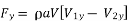
Force exerted on radial vanes
For a radial curved vane, the radius of the vane at inlet and outlet is different & hence the tangential velocities of the radial vane at the inlet and outlet are not equal.
Consider a series of radial curved vanes mounted on a wheel as shown in fig.
|

The jet of water strikes the vanes and the wheel start rotating at a constant angular speed
 Radius of wheel at the inlet of vane
 Radius of wheel at the outlet of vane
 = Angular speed of the wheel
Then, 
And 
The mass of water striking per second for a series of vane =
Where a= Area of jet
 Velocity of jet
Momentum of water striking the vanes in the tangential direction per second at inlet= Mass of water per second  Component of V in the tangential direction
=
Similarly momentum of water at outlet per second = Component of
  in the
tangential direction
= (-
(- cos
cos )
)
=
Now angular momentum per second in the inlet
=Momentum at inlet  Radius at outlet
=
Angular momentum per second at outlet
=momentum at outlet  Radius at outlet
= -
Torque exerted by the water on the wheel
T= Rate of change of angular momentum
= [Initial angular momentum per second – Final angular momentum per second]
= -(-
-(-
= +
+
Work done per second on the wheel
=Torque  Angular velocity
=T
= +
+
= +
+
= +
+
If angle  in fig. is on obtuse angle then work done per second will be given as
 -
-
General expression for the work done per second on the wheel

if the discharge is radial at outlet then  & work done becomes as
Efficiency of the radial curved vane  =
=
=
=
=
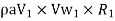
Velocity triangles and their analysis, work done equations, vane efficiency.
Fig. shows a jet of water strikes a moving curved plate (vane) tangentially at one of its tips.
|
Let
 =Velocity of the jet of inlet
 =Velocity of the vane at inlet
 =Relative velocity of jet and vane of inlet
 = Guide blade angle
(Angle between the direction of jet and direction of motion of the plate)
 Angle made by the relative velocity
  with direction of motion at inlet (vane angle at inlet )
 =The components of velocity of jet
  in the direction of motion and perpendicular to direction of motion of the vane respectively.
 = Whirl velocity at inlet
 = Flow velocity at inlet
 =Velocity of jet leaving the vane or velocity of the jet at the outlet of vane
 = Velocity of the vane at outlet
 =Relative velocity of the jet with respect to the vane
 =Angle made by the velocity
  with direction of motion of the vane at outlet
 =Vane angle at outlet
 =Whirl velocity of outlet
 =Velocity of the flow at outlet
The triangles ABD and EGF are called the velocity triangles of inlet and outlet
Velocity triangle at inlet
- Take any point A and draw line AB=
 in magnitude and direction which means line AB makes an angle
  with the horizontal line AD. Next draw a line AC =
  in magnitude. Join C to B. Then CB represents the relative velocity at the jet at inlet. If loss of energy at inlet due to impact is zero then, CB must in the tangential direction to the vane at inlet. From B draw a vertical line BD in the downward direction to meet the horizontal line AC produced at D.
Then BD= Velocity of the flow at inlet=
AD=Velocity of the whirl at inlet-
Angle BCD = Vane angle of the inlet 
2. Velocity triangle of outlet
If vane surface is assumed to be very smooth, the loss of energy due to friction will be zero. The water will be gliding over the surface of the vane with relative velocity equal to  and will come out of the vane with the relative velocity
  . Which means
  . And also relative velocity at outlet and EG=
 . From G draw a line GF in the direction of vane at outlet & equal to u2 , the velocity of vane at outlet. Join EF. Then EF represents the absolute velocity of the jet at outlet in magnitude & direction. From E draw vertical line EH to meet the line GF produced at H. Then
EH=Velocity of flow of outlet =
FH=Velocity of whirl at outlet =
 Angle of vane of outlet
 =Angle made by
  with the direction of motion of vane at outlet.
If the vane is smooth and is having velocity in the direction of motion at inlet and outlet equal then we have  = u = velocity of vane in the direction of motion

Mass flow of water striking vane= ----(1)
Where a =Area of jet of water
 Relative velocity of inlet
Force exerted by the jet in the direction of motion
 =Mass of water striking per second
 [initial velocity- final velocity] ----(2)
But initial velocity with which jet strikes the vane =
The component of this velocity in the direction of motion=
Similarly, the component of relative velocity at outlet in the direction of motion = 
Substituting the equation (1) and all above value of velocity in equation 2
 [(
[( -
- -[-
-[-
= [(
[( -
- +
+
= , because
  …….. 3
Equation (3) is true only when angle  shown in fig is an acute angle.
If  =
=  , the
, the  Then equation (3) becomes as
 [
[
If  is an obtuse angle, the expression for
  will become
 [
[
Thus in general,  is written as
 [
[
Work done per second on the vane by the jet
=Force  velocity
=
= [
[
Work done per second per unit weight of fluid striking per second
= 
= 
= 
Efficiency of jet 
=
= 
Where m=mass of fluid per second in the jet
 Initial velocity

- According to the type of energy at inlet
- impulse turbine
- reaction turbine
- According to the direction of flow through runner.
- Tangential flow turbine
- Radial flow turbine
- Axial flow turbine
- Mixed flow turbine
- According to head at inlet of turbine
- High head turbine
- Medium head turbine
- Low head turbine
- According to specific speed of turbine
- Low specific speed turbine
- Medium specific speed turbine
- High specific speed of turbine
- In an impulse turbine all available energy of water is converted into kinetic energy or velocity head by passing it through a nozzle provided at the end of penstock.
- The water coming out of the nozzle is formed into a free jet which impinges on a series of buckets of the runner does causing it to revolve.
- The runner revolves freely in air.
- The water is in contact with runner only a part of the runner at a time and throughout its action and its subsequent flow to the tale race the water is atmospheric pressure.
- A casing however provided on the runner to prevent splashing and to guide the water discharge from buckets to tail race.
|
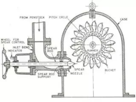
- Figure shows the elements of a typical Pelton wheel installation.
- The runner consists of a circular disc with number of buckets evenly spaced around its periphery.
- The buckets have a shape of double semi ellipsoidal cups. Each bucket is divided into two symmetrical parts by a sharp edge ridge known as splitter.
- One or more nozzles are mounted so that each directs a jet along a tangent to the circle through the centers of the buckets called the pitch circle.
- The jet of water impinges on the splitter, which divides jet into two equal portions.
- Each of which after flowing around the smooth inner surface at the buckets leaves it at its outer edge.
- The buckets are so shape that the angle at the outlet tip varies from 10 degrees to 20 degrees so that the jet of water gets deflected through 160 degrees to 170 degree.
- The back of the bucket is so shape that as its swings downwards no water is wasted by splashing.
- Further at the lower tip of the bucket a notch is cut which prevents jet striking the preceding bucket being intercepted by the next bucket very soon and is also avoid deflection of water towards the center of the wheel as the bucket first meets the jet.
- For low heads buckets are made of cast iron and for high heads they are made of cast steel bronze or stainless steel.
- In order to control the quantity of water striking the runner the nozzle fitted at the end of penstock provided with a spear or needle having a streamlined head which is fixed as shown in figure.
- A casing made of cast iron or fabricated steel plates is usually provided for a Pelton wheel as shown in figure to prevent splashing of water and also to act as a safeguard against accidents.
|
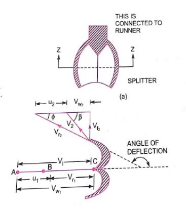
- Figure shows the shape of the veins or buckets of the Pelton wheel.
- The jet of water from the nozzle strike the bucket at the splitter which splits up the jet into two parts.
- These parts of the jet glides over the inner surfaces and comes out at the outer edge. The splitter is the inlet tip and outer edge of the bucket is the outlet tip of the bucket.
- The inlet velocity triangle is drawn at the splitter and outlet velocity triangle is drawn at the outer edge of the bucket.
H= Net head acting on the Pelton wheel
= 
 Gross head

 Dia of penstock
N= Speed of the wheel in r.p.m
D= diameter of the wheel
d=diameter of the jet
Then,  Velocity of jet at inlet

The velocity triangle at inlet will be a straight line where


 =0 and
  =0
=0
From the velocity triangular at outlet, we have

The force exerted by the of water in the direction of motion is given by equation

As the angle  is an acute angle, positive sign should be taken
a=area of jet 
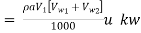
Work done by the jet on the runner per second
Power given to the runner by the jet
Work done per second per unit weight of water striking

The energy supplied to the jet at inlet is in the form of kinetic energy and is equal to 
Kinetic energy of jet per second 
Hydraulic efficiency
=

 u
u
Now 


=

Efficiencies of a Turbines: The following are the important efficiencies of a turbine.
a) Hydraulic efficiencies, ηh
b) Mechanical efficiencies, ηm
c) Volumetric efficiencies, ηv and
d) Overall efficiencies, ηo
a) Hydraulic efficiency It is defined as the ratio of power given by water to the runner of a turbine (runner is a rotating part of the turbine and on the runner vanes are fixed) to the power supplied by the water at the inlets of the turbine. The power at inlet of the turbine is more and this power goes on decreasing as the water flows over the vanes of the turbine due to hydraulic losses as the vanes are not smooth. Hence the power delivered to the runner of the turbine will be less than the power available at the inlets of the turbine. Thus mathematically, the hydraulic efficiency of the turbine is written as.
ηh = 
above R.P. = Power delivered to runner i.e., runner power
 ... for Pelton Turbine
 ... for a radial Flow Turbine
W.P. = Power supplied at inlet of turbine and also called water power
= 
Where, W = Weight of water striking the vanes of the turbine per second
= ρg × Q in which Q = Volume of water/s


u = Tangential velocity of vane
u1 = Tangential velocity of vane at inlet for radial vane
u2 = Tangential velocity of vane at inlet for radial vane
H = Net head on the turbine.
Power supplied at the inlet of turbine in S.I. units is known as water power. It is given by
W.P. =  .......................(A)
For water ρ = 1000 kg/m3
W.P. =  = g× Q× HkW .......................(B)
The relation (B) is only used when the flowing fluid is water. If the flowing fluid is other than the water, then relation (A) is used.
b) Mechanical Efficiency (ηm) The power delivered by water to the runner of a turbine is transmitted to the shaft of the turbine. Due to mechanical losses, the power available at the shaft of the turbine is less than the power delivered to the runner of a turbine. The ratio of the power available at the shaft of the turbine (known as S.P. or B.P.) to the power delivered to the runner is defined as mechanical efficiency. Hence, mathematically, it is written as
ηm = 
c) Volumetric Efficiency (ηv) The volume of the water striking the runner of a turbine is slightly less than the volume of the water supplied to the turbine. Some of the volume of the water is discharged to the tail race without striking the runner to the volume of water supplied to the turbine is defined as volumetric efficiency. It is written as
ηv = 
Overall Efficiency (ηo) It is defined as the ratio of power available at the shaft of the turbine to the power supplied by the water at the inlet of the turbine. It is written as:
ηo = 
= S.P./W.P.
- The governing of turbine is defined as operation by which the speed of the turbine is kept constant under all conditions of working.
- It is done automatically by means of governor, which regulates the rate of flow through the turbines according to the changing load conditions on the turbine.
- Governing of a turbine is necessary as a turbine is directly coupled to an electric generator which is required to run at constant speed under all fluctuating load conditions. This is only possible when the speed of the turbine is constant.
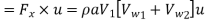
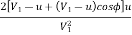
- One of the common types of governor which is predominantly used with modern turbines is oil pressure governor.
|
- As shown in figure its component parts are as follows:
1) Servo motor also known as relay cylinder.
2) Relay valve known as control valve.
3) Actuator
4) Oil sump
5) Oil pump which is driven by belt connected to turbine main shaft.
6) A system of oil supply pipes connecting the oil sump with servo motor.
- The working of the governor is explained below.
- When the load on the governor drops the speed of turbine increases.
- Now since the actuator driven by the turbine main shaft due to increase in the speed the balls move outward resulting in upward movement of the sleeve shown in figure.
- As this sleeve moves up the left-hand end of the main lever is raised, which causes the bell crank lever to move downward and simultaneously pushes the piston of the control valve in its cylinder.
- In case of a Pelton turbine the bell crank lever brings the deflector in a front of the jet thereby diverting portion of the jet away from the buckets.
- On the other hand in the case of reaction turbine such as Francis or Kaplan turbine relief valve shown in figure is provided.
- A relief valve consists of a spear which under normal condition of operation of turbine is held by oil or water under pressure in such a position that it keeps the opening of the bypass from the spiral casing to the tail race closed.
|

- The downward motion of the bell crank lever opens the pilot valve of the pressure chamber so that the pressure on the spear is reduced, thereby permitting spear to be lifted up and allowing a portion of water to flow directly from the spiral casing to the tail race through the bypass without striking the turbine runner.
- Thus both these devices deflector and relief valves have similar functions to perform.
- These eliminate the necessity of rapid closure of the nozzle opening or guide vanes, at the same time the quantity of water striking the runner is reduced.
- With downward motion of the piston of the control valve the passage for pipeline 2 opens & oil under pressure is admitted from the control valves cylinder to the servo motor on the left side of the piston.
- The servo motor piston therefore moves to right.
- In the case of Pelton wheel the servo motor piston being connected to the spear rod, thus causes the spear to move forward.
- The forward motion of the spear reduces the area of nozzle and thus decreases the rate of flow.
- However, in the case of a reaction turbine the forward motion of servo motor piston is transmitted to the regulating ring as shown in figure (b) which causes oil the guide vanes to move simultaneously in one direction and thus the area of flow passage between the adjacent guide vanes is reduced and rate of flow of water striking the runner is also reduce.
- When the load on the generator increases, the speed of the turbine runner decreases.
- Due to this the balls move inward resulting in in the downward movement of the sleeve.
- The left hand end of the main lever is lowered which puts the piston of the control valve up in the cylinder, with the upward motion of the piston pipeline 1 opens and oil under pressure rushes from the control valve cylinder to the servo motor on the right side of the piston.
- The servo motor piston then moves to the left.
- Thus increase the area of nozzle outlet or passage between the adjacent guide vanes there by allowing a large quantity of water to strike the runner and the normal speed for the turbine runner is thus restored.
Numerical
1. A 7.5cm diameter jet having a velocity of 30 m/s strikes a flat plate , the normal of which inclined at  to the axis of the jet .Find the normal pressure on the plate.
- When the plate is stationary
- When the plate is moving with velocity of 15m/s and away from the jet.
Also determine the power and efficiency of the jet when the plate is moving.
- Solution
Diameter of the jet = 7.5cm=0.075m
Area of the jet = (0.75)2 =0.04417
Angle between the jet and plate =  =
=
Velocity of jet 
- When the plate is stationary the normal force on the plate

= 
2. When the plate is moving with a velocity  and away from the jet the normal force on the plate

= 
 496.9N
Work done per second by the jet = force in the direction of jet x Distance moved by the plate
in the direction of jet/sec 
= 496.9 x 15= 7453.5 Nm/s
Power in kW= =
=  = 7.453 KW
Efficiency of the jet =
= 
= 0.1249=12.5%
2. A jet of water having a velocity of 20m/s strikes a curved vane which is moving with a velocity of 10m/s . The jet makes an angle of  with the direction of motion of vane at inlet and leaves at an angle of
  to direction of motion of motion of vane an outlet. Calculate:
- Vane angles so that the water enters and leaves the vane without shock
- Work done per second per unit weight of water striking
Given


 in triangle ABD we have

Where 


From triangle ABC


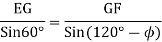
From triangle EFG applying sine rule
We have 


Work done per second per unit weight of the water striking the vane per second
= 
Where 


Work done per unit weight of water
= 
3. A jet of water of diameter 50 mm, having a velocity of 20m/s strikes a curved vane which is moving with a velocity of 10m/s in the direction of the jet. The jet leaves the vane at an angle of 60 to the direction of motion of vane at outlet determine:
1) The force exerted by the jet on the vane in the direction of motion.
2) Work done per second by the jet.
- Solution
Diameter of the jet d= 50mm=0.05 m
Area, a=
Velocity of jet ,
Velocity of vane, 
As jet and vane are moving to the same direction 
Angle made by the leaving jet with the direction of motion 


From figure we have

= 20-10 =10m/s
 = 20m/s
 =10m/s
Now in  EFG, EG =
 =10m/s
GF= =10m/s

From sine rule we have,


Now ,  = HF - GF=GH
= -
- cos
cos =10 -10
 cos
cos =10 - 5 = 5 m/s
The force exerted by the jet on the vane in the direction of motion
 ( negative sign as
  is an obtuse angle)
= 1000 0.001963
 10[20 - 5] = 294.45N
Work done per second by the jet
 u=294.45
 10=2944.5 N m/s
=2944.5 W
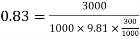
4. A Pelton turbine develops 3000 kW power under the head of 300 m. The overall efficiency of the turbine is 83%. If the ratio is 0.46 coefficients of nozzles 
i) diameter of the turbine
ii) Diameter of the jet
P=3000 kW
H=300m


Find D and d.
Sol. 
16.5= 
N= 376.11 r.p.m

= 0.98×√2×9.81×300
= 75.18 m/s
u=Ku
= 0.45×√2×9.81×300
=34.52 m/s


D=1.75 m
 =
= 
Q=1.228
Q = A×
1.228 = 
d=0.144 m
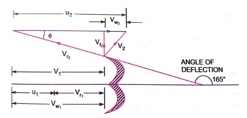
5. The mean bucket speed of a Pelton wheel is 40 m/s and discharge is 1.2 The head over the turbine is 385 m. The head loss due to friction in penstock is 9 m. The bucket deflects the jet through 165°. If coefficient of velocity of nozzle is 0.9, determine
i) Power developed by the turbine
ii) Hydraulic efficiency of turbine neglect bucket friction.
Sol.
u=
Q= 1.2
Hg=385m
 = 9m
= 9m
 = 180-165=15°
 =0.9
=0.9
Net head available = H = 
= 385 - 9
= 376 m
|

=
= 77.30m/s


= 77.30-40
= 37.30 m/s
 37.30 m/s


=40 - 36.03
= 3.97 m/s
 =
= u
u
=
=0.9817
=98.17%
Power developed =  Q
Q
=1000×1.2[77.30-3.97]
=3.52×
=3520 KW
6. A Pelton wheel is working under a head at 300m and mean bucket speed of 10m/s. Discharge through the turbine is 700 lit/sec. The buckets deflect the jet through an angle of 160°. Calculate power given by water to the runner and hydraulic efficiency of the turbine. Assume coefficient of velocity as also calculate overall efficiency and shaft power if mechanical efficiency is 85%.
Sol. H=300m


|


= 
= 75.18m/s

= 75.18 - 10
= 65.18m/s

= 61.25m/s


= 61.25 - 10
= 51.25m/s
Power given by water to the runner
(Runner power)=
=1000 x 0.7 [75.18 + 51.25] x 10
= 885.01

=
= 0.4473
= 44.73%

Shaft power =  watts
watts
Overall efficiency=
= 0.85  0.44
0.44
= 0.374
=37.4%
Ques
7. A Pelton wheel is to be designed for a head of 60m when running at 200 rpm . The Pelton wheel develops 95.6475 KW Shaft power the velocity of buckets =0.45 times the velocity of the jet , overall efficiency = 0.85 & coefficient of the velocity is equal to 0.98.
Solution
H=60m
N=200m
S.P.= 95.6475 KW
u = 0.45 V


= 
= 33.62m/s
 = 0.45 V
= 0.45 x 33.62
=15.13m/s


D=1.44m


Q=0.1912
Q=A x 


Width of buckets=5d=5 x 85
=425mm
Depth of buckets=1.2d=1.2 x 85
=102mm
Number of buckets=
= 23.5 = 24
- Hydraulics & Fluid mechanics – Modi & Seth
- Fluid mechanics & hydraulic machines. – R.K. Bansal
- Turbomachines – B.U. Pai


