Unit-2
Design of Shaft
Shaft is a rotating machine element which is used to transmit power from one place to another. In order to transfer the power from one shaft to another, the various member such as pulleys, gears etc.
It is the machine members, mostly cylindrical in cross-section, which support the revolving parts of a machine, such as pulleys, gear, flywheels etc.
The following stresses are induced in the shafts:
- Shear stresses due to the transmission of torque (due to torsional load).
- Bending stresses (tensile or compressive) due to the forces acting upon the machine elements like gears and pulleys as well as the self weight of the shaft.
- Stress due to combined torsional and bending loads.
|
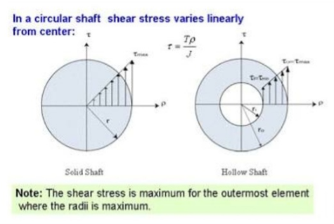
Figure 1: stresses generated in shaft
Key takeaways
Torsional load, bending load and torsional-bending load are the kinds of stresses that is exerted on the shaft.
The static load safety factor is calculated by dividing the basic static load rating (C0) by the static equivalent load of the most heavily loaded bearing.
When the shaft is subjected to a twisting moment (or torque) only, then the diameter of the shaft only may be obtained by using the torsion equation. We know that T/J=Ϡ/r……………………………..(i) Where, T= twisting moment acting on the shaft J=Polar moment of inertia Ϡ= Torsional shear stress R= distance from neutral axis to the outermost fibre =d/2, where d is the diameter of shaft
|

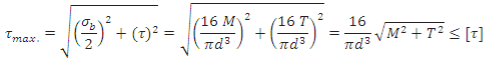
When the shaft is subjected to combination of torque and bending moment, principal stresses are calculated and then different theories of failure are used. Bending stress and torsional shear stress can be calculated using the above relations.
Maximum Shear Stress Theory Maximum shear stress is given by,
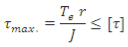
Maximum Principal Stress Theory Maximum principal stress is given by,
|


Key takeaways
Maximum shear stress theory and maximum principle stress theory is the major stress which acts in combination while designing of a shaft.
When shaft rotates, bending stress changes from tensile to compressive and then compressive to tensile, ie, completely reversing state of stress. Fa will give rise to normal axial stress in the shaft.
The driving forces and the driven resistances result in bending of the shaft and, for helical gearing, an axial loading is also produced. These loadings generate both normal and shear stresses in the shaft. The torsion loading produces a maximum shear stress at the shaft surface calculated from. fs=T rJ.
A shaft is a part of a machine or system of machines, and is used to transmit power by virtue of its torsional strength, or resistance to twisting. Shafts are almost always made of metal and are usually circular in cross-section, being sometimes made hollow.
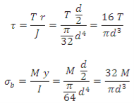
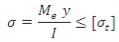
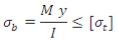
Shaft design based on the deflection: Maximum bending stress developed in a shaft is given by,
where M = Bending Moment acting upon the shaft, I = Moment of inertia of cross-sectional area of the shaft about the axis of rotation = = y = Distance from neutral axis to the outer most fibre = d / 2 (or do/2) So dimensions of the shaft subjected to bending moment can be determined from above relation for a known value of allowable tensile stress. Design of shaft on the strength basis: Transmission shafts are subjected to axial tensile force, bending moment or torsional moment or their combination. Most of the transmission shafts are combined bending and torsional moment. The design of transmission shafts means finding diameter or inner or outer diameter in case of hollow shaft from the strength and rigidity consideration. Design of shaft subjected to pure axial load. Let P be the axial load d = required diameter of the shaft σt=permissible tensile load σt= P/A=(P)/(πd2/4) or, σt=(4P)/(πd2) or, d= for hollow shaft σt=(P)/(π(do2- di2/4) Shaft subjected to pure bending moment σb=Mby/I σb=32Mb/πd3 For hollow shaft I=(π(do4- di4)/64 Shaft subjected to pure torsional moment, the torsional shear stress is given by Ϡ=Tr/J For solid shaft It is, 16T/πd3 In case of hollow shaft J=(π(do4- di4)/32 |


The critical speed is the theoretical angular velocity which excites the natural frequency of a rotating object, such as a shaft. As the speed of rotation approaches the objects natural frequency, the object begins to resonate which dramatically increases systemic vibration.
|
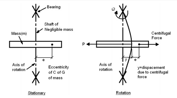
Figure 2: Stationary and rotating shafts
For a rotating shaft if the centripetal force is equal to the elastic restoring force, the deflection increases greatly and the shaft is said to "whirl”
Below and above this speed this effect is not pronounced
This critical (whirling speed) is dependent on: –
- The shaft dimensions –
- The shaft material and –
- The shaft loads
The factor which affects the critical speed of a shaft is diameter of the disc, span of the shaft, and eccentricity.
For linear motion:
Power = F.v (force x velocity)
For rotational motion
Power P = Torque x angular velocity
= T (in-lb).w (rad/sec) in-lb/sec
= T.(2 p n/60) in-lb/sec [n=rpm]
= T.(2 p n/(60*12*550)) HP [HP=550 ft-lb/sec]
= T.n/63,025 HP
or, T= 63,025HP/n (in-lb), where n = rpm
Similarly, T= 9,550,000kW/n (N-mm), where n = rpm
Sliding contact bearing: In this bearing, the sliding action takes place along the surface of contact between the moving element and fixed element. The sliding contact bearing is known as plain bearing.
|

Figure 3: Sliding contact bearing
Rolling contact bearing: In this type of bearing, steel balls or rollers are interposed between the working surfaces. These bearings are also known as anti-friction bearings due to less friction imposed on moving element.
|
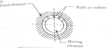
Figure 4: Roller contact bearing
In rolling contact bearings, the contact between the bearing surfaces is rolling instead of sliding as in sliding contact bearings. Sliding contact bearing starts from rest with practically metal-to-metal contact and has a high coefficient of friction.
Desirable properties of material for designing a bearing:
- Should not stick or weld to the journal surface in case of metal to metal contact
- Should have high compressive strength
- Should have high fatigue strength
- Should have high ‘Conformability’ (ability to adapt shape of journal)
- Should have high ‘Embeddability’ (accommodating dirt particles in oil)
- Should have high ‘Bondability’ (ability to bond with high strength steel shell)
- Should have sufficient corrosion resistance
- Should have high thermal conductivity and low thermal expansion
- Should have low coefficient of friction
- Should be of reasonable cost and easily available
Bearing design selection parameters:
- Length to diameter ratio (L/D)
- Unit Bearing Pressure
- Start up load
- Radial clearance
- Minimum oil film thickness
- Maximum oil film temperature
- Length to diameter ratio:
- Length to diameter ratio affects the performance of the bearing
- A long bearing has more load carrying capacity but are more susceptible to metal to metal contact
- A short bearing has greater side flow
- L/D > 1 (long bearing)
- L/D < 1 (short bearing)
- L/D = 1 (square bearing)
b. Unit bearing pressure:
- It is load per unit of projected area of the bearing in running condition •
- It depends on bearing materials, operating temperature, nature and frequency of load and service conditions.
- The values of unit bearing pressure based on past experience are provided in the design data book.
c. Start up load:
- It is static load when the shaft is stationary
- Mainly consist of dead weight of shaft and its accessories
- The unit bearing pressure for the starting conditions should not exceed 2 MPa
d. Radial clearance (c):
- Should be small to provide the necessary velocity gradient
- This requires:
- Costly finishing operations
- Rigid mounting of the bearing assembly
- Clean lubricating oil without any foreign particle
- Practical value of c is 0.001 r Material Radial clearance Babbits 0.001 r to 0.00167 r Copper lead 0.001 r to 0.01 r Aluminium alloys 0.002 r to 0.0025 r
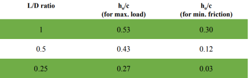
e. Minimum oil film thickness (h0 ) :
- The surface finish of the journal and the bearing is governed by the value of minimum oil film thickness selected by the designer and vice versa.
- There is a lower limit for the minimum oil film thickness below which metal to metal contact occurs and hydrodynamic film breaks
- The lower limit is given by h0 = 0.0002 r
f. Maximum oil film temperature:
- The lubricating oil tends to oxidize when operating temperature exceeds 120°C
- Also the surface of the bearing material tends to soften at 125°C
- Therefore, operating temperature should be kept within limits
- The limiting temperature is 90°C for bearings made of Babbit material
|
Reference:
- R. S Khurmi: A text book of machine design.
- Power point presentations from google and other helpful documents.
- Shubham Tyagi and Hareesh kumar for machine design


