Unit 3
Electromagnetism
The MMF is defined as the work done in moving the unit magnetic pole (1weber) once around the magnetic circuit.
The magnetomotive force (MMF) is required to drive the magnetic flux in the magnetic circuit. The magnetic pressure, which sets up the magnetic flux in the circuit as called Magnetomotive Force. The SI unit of MMF is Ampere-turn (AT), and their CGS unit is G (gilbert). The MMF for the inductive coil shown in the figure below is expressed as
F=NI
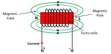
The strength of the MMF is equivalent to the product of the current around the turns and the number of turns of the coil.
Magnetic Flux:
The number of magnetic lines of forces set up in a magnetic circuit is called Magnetic Flux. It is analogous to electric current, I in an electric circuit. Its SI unit is Weber (Wb) and its CGS unit is Maxwell. It is denoted by φB.
ΦB=B.S
ΦB=B.S Cos
B – the magnitude of the magnetic field
S – area of surface
θ – angle between the magnetic field lines and perpendicular distance normal to the surface area
Magnetic flux for a closed surface
ΦB= =0
=0
Magnetic flux for open surface is
E=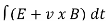
E=
E – Electromotive force
v – velocity of the boundary
E – electric field
B – magnetic field
øB - magnetic flux through the open surface
The magnetic flux through a closed surface is always zero, but in the open surface, it is not zero.
Magnetic Reluctance:
The obstruction offered by a magnetic circuit to the magnetic flux is known as reluctance.

S=
l – the length of the conductor
μo – permeability of vacuum which is equal to 4π Χ10-7 Henry/metre.
μr – relative permeability of the material.
A – cross-section area of the conductor.
Its SI unit is AT / Wb (ampere-turns / Weber)
Flux density
It is defined as the flux passing per unit area through a plane at right angles to the flux. It is denoted by B. Its unit is Weber/m2.
B=  Wb/m2
Wb/m2
Flux intensity/Magnetic Field Strength
Is is also known as magnetic field strength. It is numerically equal to the force experienced by the N-pole of one weber placed at that point. It is denoted by H.
H=  A/m or N/Wb
Reluctance
The obstruction offered by a magnetic circuit to the magnetic flux is known as reluctance.
S=
l – the length of the conductor
μo – permeability of vacuum which is equal to 4π Χ10-7 Henry/metre.
μr – relative permeability of the material.
A – cross-section area of the conductor.
Its SI unit is AT / Wb (ampere-turns / Weber)
Permanence
Every medium is supposed to have two permittivities.
a) Absolute permitivitty 
b) Relative permittivity  r
r
To measure  r vaccum or free space is chosen. It has an absolute permittivity of 8.854 x 10⁻¹² F/m. For any other medium
 =
=  0
0  r
r
Permeability
The phenomenon of magnetism and electromagnetism depends on certain property of material called as permeability. Every medium is supposed to have two permeabilities.
a) Absolute permeability 
b) Relative permeability  0
0
To measure  r vacuum or free space is chosen. It has an absolute permeability of 4
 x 10-7 H/m. For any other medium
 =
=  0
0  r
r
Que) The amount of flux present in around magnetic bar was measured at 0.013 weber. If the material has a diameter of 14cm, calculate the flux density.
Sol: Area= r2
r2
Diameter=2r
r=14/2=7cm=0.07m
Area=3.14 x 0.072=0.0154m2
Flux Density B== A=0.013/0.0154=0.843 Tesla
Que) Calculate the radius of the material having flux density of 0.5 T and flux present around the magnetic bar is 0.02T.
Sol: Flux Density B= A
A
A= B=0.02/0.5=0.04 m2
Area= r2
r2
r=0.113m
Que) A wire 2.5m long is bent into a square and into a circle. If the current flowing through the wire is 100 A, find the magnetising force at the centre of the square and the centre of the circle?
Sol: Value of h at centre of square will be H= =
=  =144 AT/m
Value of H at the centre of circle is H=I/2 r
r
=125.6AT/m
Que) Calculate the magnetising force and flux density at a distance of 4cm from a long straight circular conductor carrying a current of 250A and placed in air?
Sol: H=I/2 r
r
=250/2 x 0.04=994.71 AT/m
B=μoH
=4 x10-7x994.71=1.25x10⁻³ Wb/m2
The magnetic field exerts a force on a current carrying wire in the direction given by right hand rule. The force on a charge moving with vd velocity is
F=q vdBsin 
B is uniform over the length of the wire and zero otherwise.
F= (q vdBsin  )N
)N
N: number of charge carriers in the wire
N=nV
n=number of charge carrier /unit volume
V= volume of wire in the field
V=AI
A=cross-sectional area
F= (q vdBsin )nAl
)nAl
F= nqAvd)lBsin
F= I l Bsin 
Fleming’s Left-hand rule
When a current carrying conductor is placed inside a magnetic field, a force acts on the conductor in a direction perpendicular to both the directions of the current and the magnetic field. If the forefinger represents the direction of the field and the second finger represents that of the current, then thumb gives the direction of the force.
Fleming’s Right-hand rule
From Faraday’s Law when a conductor moves inside a magnetic field an induced current is always there. If this conductor is forcefully moved inside the magnetic field, then relation between applied force direction, magnetic field and current can be seen This relation is determined by Fleming’s right-hand Rule.
Hold out the right hand with the first finger, second finger and thumb at the right angle to each other. If forefinger represents the direction of the line of force, the thumb points in the direction of motion or applied force, then second finger points in the direction of the induced current.
In a magnetic circuit, this field is represented by magnetomotive force. It is analogous to the electromotive force in electrical circuit. This field is responsible to “set up” certain flux, which in turn gives rise to certain flux density B. Note that, here H is cause and B is its effect. The amount of flux which can be setup in a material is determined by an inherent property of the material, called as permeability, denoted by µ.
B = µH
When external magnetic field H is applied to a material, all the domains align in a particular direction, setting up net flux in the material. Due to domain alignment B (i.e. the magnitude of B) increases. However, after a certain value of B, the slope of B − H curve starts reducing as shown in Figure below
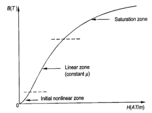
Fig: Magnetization curve
We cannot measure B and H directly. Further if we have transformer, we only have terminal measurements are with us. Hence, it is required to process the signals to get values of B and H. From Faraday’s law, V = N dφ/dt . Also, B is directly proportional to flux φ.
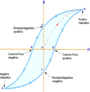
Fig: B-H curve
The lag or delay of a magnetic material known commonly as Magnetic Hysteresis. The Magnetic Hysteresis loop above, shows the behaviour of a ferromagnetic core graphically as the relationship between B and H is non-linear. Initially both B and H will be at zero, point 0 on the magnetisation curve.
If the magnetisation current, i is increased in a positive direction to some value than the magnetic field strength H increases linearly with i and the flux density B also increases (curve from point 0 to point a) as it heads towards saturation.
Now if the magnetising current in the coil is reduced to zero, the magnetic field circulating around the core also reduces to zero. However, the coils magnetic flux will not reach zero due to the residual magnetism present within the core and this is shown on the curve from point a to point b.
To reduce the flux density at point b to zero we need to reverse the current flowing through the coil. The magnetising force which must be applied to null the residual flux density is called a “Coercive Force”. This coercive force reverses the magnetic field re-arranging the molecular magnets until the core becomes unmagnetized at point c.
An increase in this reverse current causes the core to be magnetised in the opposite direction and increasing this magnetisation current further will cause the core to reach its saturation point but in the opposite direction, point d on the curve.
This point is symmetrical to point b. If the magnetising current is reduced again to zero the residual magnetism present in the core will be equal to the previous value but in reverse at point e.
Again, reversing the magnetising current flowing through the coil this time into a positive direction will cause the magnetic flux to reach zero, point f on the curve and as before increasing the magnetisation current further in a positive direction will cause the core to reach saturation at point a.
Then the B-H curve follows the path of a-b-c-d-e-f-a as the magnetising current flowing through the coil alternates between a positive and negative value such as the cycle of an AC voltage. This path is called a Magnetic Hysteresis Loop.
Faraday’s Laws of Electromagnetic Induction consists of two laws. The first law describes the induction of emf in a conductor and the second law quantifies the emf produced in the conductor
i) Faradays First law of EMI: Whenever a conductor is placed in a varying magnetic field, an electromotive force is induced. If the conductor circuit is closed, a current is induced which is called induced current.
Ii) Faradays Second law of EMI: The induced emf in a coil is equal to the rate of change of flux linkage.

 = electromotive force
N = Number of turns
 = magnetic flux
- Increase in the number of turns in the coil increases the induced emf
- Increasing the magnetic field strength increases the induced emf
- Increasing the speed of the relative motion between the coil and the magnet, results in the increased emf.
What is Self Induction?
When there is a change in the current or magnetic flux of the coil, an opposed induced electromotive force is produced. This phenomenon is termed as Self Induction. When the current starts flowing through the coil at any instant, it is found that that the magnetic flux becomes directly proportional to the current passing through the circuit. The relation is given as:
ϕ= I
ϕ = L I
Where L is termed as self-inductance of the coil or the coefficient of self-inductance. The self-inductance depends on the cross-sectional area, the permeability of the material or the number of turns in the coil.
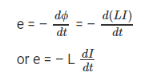
The rate of change of magnetic flux in the coil is given as,
What is Mutual Induction?
We take two coils, and they are placed close to each other. The two coils are P- coil (Primary coil) and S- coil (Secondary coil). To the P-coil, a battery, and a key is connected wherein the S-coil a galvanometer is connected across it. When there is a change in the current or magnetic flux linked with two coils an opposing electromotive force is produced across each coil, and this phenomenon is termed as Mutual Induction. The relation is given as:
ϕ = I
ϕ = M I
Where M is termed as the mutual inductance of the two coils or the coefficient of the mutual inductance of the two coils.
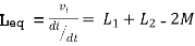
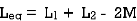
The rate of change of magnetic flux in the coil is given as,
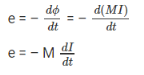
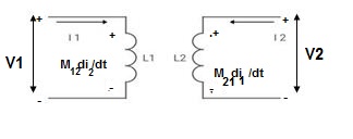
- MUTUAL INDUCTANCE:-
 mutual inductance on 1 due to 2
 mutual inductance on 2 due to 1
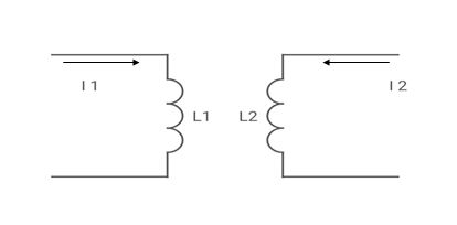
● If current is entering at dot  then it will produce mutual induction or it will produce a voltage with positive polarity on
  .
.
● If current is leaving at dot  then it will produce a voltage with negative polarity on
  .
.
Voltage on 2 due to 1 = 
Voltage on 1 due to 2 = 
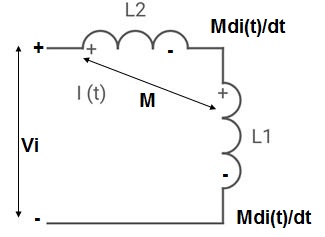
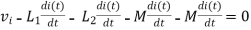
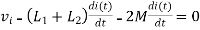
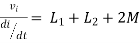
- When current is entering or leaving from both dots.
 -
-  -
-  = 0 ⎼⎼⎼⎼⎼⎼ 1
 -
-  -
-  = 0 ⎼⎼⎼⎼⎼⎼2

 -
-  -
-  = 0 ⎼⎼⎼⎼⎼⎼⎼1
 -
-  = 0 ⎼⎼⎼⎼⎼⎼⎼2
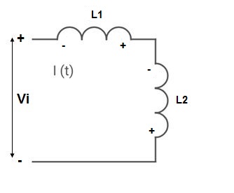
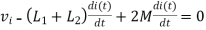
2. When current is entering from one dot and leaving the other

 -
-  +
+  = 0 ⎼⎼⎼⎼⎼⎼⎼⎼1
 -
-  +
+  = 0 ⎼⎼⎼⎼⎼⎼⎼⎼2
- When current is entering in both dots
Find 
If 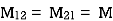

II. When current leaves both dots
 Find
Find 
III. When current enters from  and leaves
 Find
Find 
IV. When current leaves  and enters

Example 1. Find 


Example 2. Find 
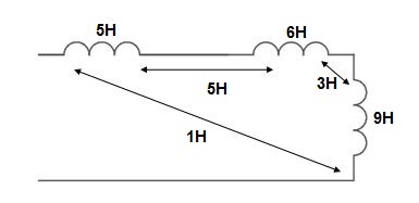


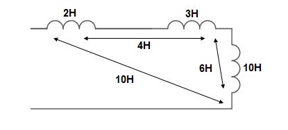
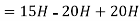
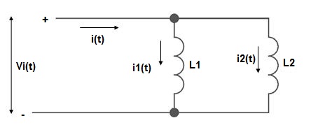
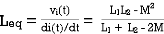
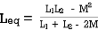
PARALLEL COMBINATION: -


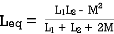


Magnetic field can be of permanent magnet or electro-magnet. Both magnetic fields store some energy. Permanent magnet always creates the magnetic flux and it does not vary upon the other external factors. But electromagnet creates its variable magnetic fields based on how much current it carries. The dimension of this electro-magnet is responsible to create the strength the magnetic field and hence the energy stored in this electromagnet.
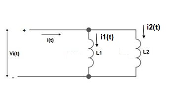
First we consider the magnetic field is due to electromagnet i.e. a coil of several no. Turns. This coil or inductor is carrying current I when it is connected across a battery or voltage source through a switch.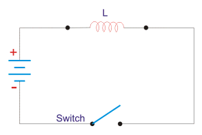
Suppose battery voltage is V volts, value of inductor is L Henry, and current I will flow at steady state.
When the switch is ON, a current will flow from zero to its steady value. But due to self induction a induced voltage appears which is
this E always in the opposite direction of the rate of change of current.
Now here the energy or work done due to this current passing through this inductor is U.
As the current starts from its zero value and flowing against the induced emf E, the energy will grow up gradually from zero value to U.
dU = W.dt, where W is the small power and W = – E.I
So, the energy stored in the inductor is given by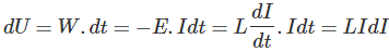
Now integrate the energy from 0 to its final value.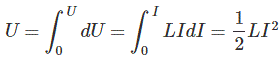
Again,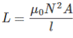
as per dimension of the coil, where N is the number of turns of the coil, A is the effective cross-sectional area of the coil and l is the effective length of the coil.
Again,
Where, H is the magnetizing force, N is the number of turns of the coil and l is the effective length of the coil.
Now putting expression of L and I in equation of U, we get new expression i.e.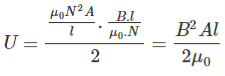
So, the stored energy in a electromagnetic field i.e. a conductor can be calculated from its dimension and flux density.
Reference’s
1.Theory and Problems of Basic electrical Engineering : Nagrath Kothri
2.Electrical technology by B.L.Theraja, A.K.Theraja: S chand publication
3.Basic Electrical Engineering : V K Mehta
4.Basic Electrical Engineering : S K Sahdev: Pearson publication
5.Electrical Safety, Fire Safety engineering S.Rao, Khanna Publication


