Back to Study material
TE

Unit-4

Highway Materials


4.1 Properties of Subgrade

4.1.1 Introduction

  • Soil is an accumulation or deposit of earth material, derived naturally from the disintegration of rocks or decay of vegetation that can be excavated readily with power equipment in the field or disintegrated by gentle mechanical means in the laboratory.
  • The supporting soil beneath pavement and its special under courses is called sub grade.
  • Undisturbed soil beneath the pavement is called natural sub grade.
  • Compacted sub grade is the soil compacted by controlled movement of heavy compactors.
  • 4.1.2 Desirable Properties of Subgrade Soil

  • Stability
  • Incompressibility
  • Permanency of strength
  • Minimum changes in volume and stability under adverse conditions of weather and groundwater
  • Superior drainage
  • Ease of compaction
  • 4.1.3 Soil Types

    Gravel

    Sand

    Silt

    Clay


    Coarse

    Medium

    Fine

    Coarse

    Medium

    Fine

    Coarse

    Medium

    Fine


               0.6mm      0.2mm

           0.02mm       0.006mm

    0.0006mm       0.0002mm

    2mm

    0.06mm

    0.002mm


  • Gravel: These are coarse materials with particle size under 2.36 mm with little or no fines contributing to cohesion of materials.
  • Moorum: These are products of decomposition and weathering of the pavement rock. Visually these are similar to gravel except presence of higher content of fines.
  • Silts: These are finer than sand, brighter in color as compared to clay, and exhibit little cohesion. When a lump of silty soil mixed with water, alternately squeezed and tapped a shiny surface makes its appearance, thus dilatancy is a specific property of such soil.
  • Clays: These are finer than silts. Clayey soils exhibit stickiness, high strength when dry, and show no dilatancy. Black cotton soil and other expansive clays exhibit swelling and shrinkage properties. Paste of clay with water when rubbed in between fingers leaves stain, which is not observed for silts.
  • 4.1.4 Tests on Soil

  • Sub grade soil is an integral part of the road pavement structure as it provides the support to the pavement from beneath.
  • The main function of the sub grade is to give adequate support to the pavement and for this the sub grade should possess sufficient stability under adverse climatic and loading conditions. Therefore, it is very essential to evaluate the sub grade by conducting tests.
  • The tests used to evaluate the strength properties of soils may be broadly divided into three groups:
    • Shear Tests
    • Bearing Tests
    • Penetration Tests
  • Shear Tests: are usually carried out on relatively small soil samples in the laboratory. In order to find out the strength properties of soil, a number of representative samples from different locations are tested.
  • Some of the commonly known shear tests are direct shear test, triaxial compression test, and unconfined compression test.
  •  

  • Bearing Tests: are loading tests carried out on sub grade soils in-situ with a load bearing area. The results of the bearing tests are influenced by variations in the soil properties within the stressed soil mass underneath and hence the overall stability of the part of the soil mass stressed could be studied.
  • Penetration Tests: may be considered as small scale bearing tests in which the size of the loaded area is relatively much smaller and ratio of the penetration to the size of the loaded area is much greater than the ratios in bearing tests. The penetration tests are carried out in the field or in the laboratory.
  • Key Takeaways:

  • Undisturbed Soil: - An undisturbed sample is one where the condition of the soil in the sample is close enough to the conditions of the soil in-situ to allow tests of structural properties of the soil to be used to approximate the properties of the soil in-situ.
  • Disturbed Soil: - Soil that has been changed from its natural condition by excavation or other means.
  •  


    4.2 Aggregates & Binding materials

    4.2.1 Aggregates

  • Aggregates form the major portion of the pavement structure, bear stresses occurring on the roads and have to resist wear due to abrasive action of traffic.
  • Aggregates are also used in flexible as well as in rigid pavements. Therefore, the properties of aggregates are of considerable importance to highway.
  • The aggregates are specified based on their grain size, shape, texture and gradation.
  • Based on the strength property, the coarse aggregates maybe divided as hard aggregates or soft aggregates (Moorum, kankar, laterite, brick aggregates).
  • 4.2.2 Desirable Properties of Road Aggregates

    Strength

  • The aggregates to be used in road construction, particularly the aggregates used in the wearing course of the pavement should be sufficiently strong/ resistant to crushing to withstand the high stresses induced due to heavy traffic wheel loads.
  • Hardness

  • The aggregates used in the surface course are subjected to constant rubbing or abrasion due to moving traffic.
  • Abrasive action may be increased due to the presence of abrasing material like sand between the tyres of vehicle and the aggregates exposed to the top surface. Thus, they should be hard enough to resist the wear due to abrasive action of traffic.
  • Toughness

  • Aggregates in the pavement are also subjected to impact due to moving wheel loads. The magnitude of impact increase with roughness of road and speed of vehicle.
  • Severe impact is common when heavily loaded steel tyred vehicles move on WBM. The resistance to impact or toughness is thus another desirable property of aggregates.
  • Durability

  • The aggregates used in roads are subjected to physical and chemical actions of rains and ground water, the impurities in them and that of atmosphere. Thus it is desirable that the road stones used in the construction should be sound enough to withstand the weathering action.
  • The property of aggregates to withstand the adverse actions of weather may be called soundness.
  • Shape of Aggregates

  • Road aggregates may be rounded, angular, flaky or elongated.
  • Flaky and elongated particles have less strength than rounded and cubical particles. Thus, too flaky and too much elongated particles should be avoided.
  • Adhesion with Bitumen

  • The aggregates in bituminous pavements should have less affinity with water when compared with bitumen; otherwise the bituminous coating on the aggregates will be stripped off in presence of water.
  • Binding Material

  • In flexible pavements, normally bituminous binders are used as pavement binders whereas in cement concrete pavements, the binder used is cement and other stabilized layers, lime and other types of binders can be used.
  • Different bituminous binders used are
    • Bitumen
    • Tar
    • Cutback
    • Emulsion
    • Modified Binders.
  • 4.2.3 Bitumen

  • Bitumen refers to the viscous liquid or solid consisting essentially of hydrocarbons and their derivatives.
  • Bitumen is soluble in Carbon Disulphide C2S
  • Substantially non volatile
  • Softens when heated
  • Black or brown in color.
  • Petroleum Bitumen: Obtained by refining process of petroleum
  • Natural Bitumen: Occurring as natural deposits
  • Straight Run Bitumen: Petroleum bitumen whose viscosity has not been adjusted by blending or by softening with cutbacks or other methods.
  • Blown Bitumen: Straight run bitumen further treated by blowing air through it while it is in hot condition.  
  • Composition of Bitumen:

  • Complex chemical mixture of molecules that are predominantly hydrocarbons.
  • Carbon

    82-88%

    Hydrogen

    8-11%

    Sulphur

    0-6%

    Oxygen

    0-1.5%

    Nitrogen

    0-1%

  • Traces of metal: Vanadium, Nickel, Iron, Calcium, Magnesium
  • Bitumen constituents are broadly classified as Asphaltenes, Resins and oils 
  •  

  • Asphaltenes
  • Dark brown friable solids
  • Have high polarity and interact or associate more actively
  • Mainly responsible for viscosity of bitumen
  • Higher Asphaltenes content result in harder, viscous bitumen with low penetration and high softening point
  • Resins
  • Dark, Semi solid to solid
  • Fluid when heated and brittle when cold
  • Disperses the Asphaltenes throughout the oils to provide a homogenous liquid
  • Yields Asphaltenes on oxidation
  • Oils
  • Colorless liquids
  • Yields Asphaltenes and resins on oxidation
  • Bitumen is considered to be a colloidal system consisting of Asphaltenes, resins and oils.
  •  

    Key Takeaways:

  • Elongation Index: - Elongation index of an aggregate is the percentage by weight of particles whose greatest dimension (length) is greater than one and four-fifth times (1.8 times or 9/5 times) their mean dimension. It is measured on particles passing through mesh size of 63mm and retained on mesh size of 6.3mm.
  • Flakiness Index: - The flakiness index is defined as the percentage (by mass) of stones in an aggregate having an ALD of less than 0.6 times their average dimension. 
  •  


    4.3 Various tests and specification

    4.3.1 Tests on Aggregates

    1. Crushing Test

  • Aggregate crushing value gives the Crushing strength of aggregate up to which it can bear the load without fail. To conduct crushing strength test we need compression testing machine, cylindrical measure, plunger and sieves.
  • First sieve the sample aggregate, aggregate passing 12.5mm sieve and retaining 10mm sieve is oven dries at 100-110oC for 3-4 hrs.
  • The cylinder is filled with aggregate in 3 layers, 25 strokes of tampering for each later. Note down its weight (W1) and insert the plunger and placed it on compression testing machine.
  • Apply the load at uniform rate of 40 tones load in 10 minutes. Then stop the machine and crushed aggregate is sieved through 2.36mm sieve and aggregate passing 2.36mm sieve is weighed (W2).
  • Aggregate Crushing Value can be obtained by
  • A value less than 10 signifies an exceptionally strong aggregate while above 35 would normally be regarded as weak aggregates.
  •  


    2. Abrasion Test

  • Hardness property of aggregate is determined by conducting abrasion test. Los Angeles abrasion testing machine is used to conduct this test.
  • For this test, the sample taken should be clean and dried.
  • The sample is weighed W1 and placed in Los Angeles testing machine and the machine is operated.
  • Machine should be rotated at a speed of 20-33 revolutions per minute. After 1000 revolutions the sample is taken out and sieved through 1.7mm sieve.
  • Sample retained on 1.7mm is washed and dried and note down its weight W2.
  • Aggregate Abrasion Value can be obtained by
  • A maximum value of 40 percent is allowed for WBM base course in Indian conditions. For bituminous concrete, a maximum value of 35 is specified.
  • Fig.1: Abrasion Test


    3. Impact Test

  • Impact value of aggregate will give aggregate capability against sudden loads or forces.
  • For this test also aggregate passing through 12.5mm and retained on 10mm sieve is taken and oven dried.
  • Fill the cylinder with aggregate in 3 layers, 25 strokes of tamping for each layer. Weight W1 noted.
  • The cylinder is placed in impact testing machine which consist a hammer. After placing the cylinder, hammer is raised to 380mm and release freely.
  • Then it will blow the aggregates. Repeat it for 15 such blows. After that take down the sample and aggregate passing through 2.36mm sieve is weighed as W2.
  • Fig.2: Impact Test


  • Aggregates to be used for wearing course, the impact value shouldn’t exceed 30 percent. For bituminous macadam the maximum permissible value is 35 percent. For Water bound macadam base courses the maximum permissible value defined by IRC is 40 percent.
  •  

    4. Soundness Test

  • To determine the weathering resistance of aggregate soundness test is conducted. If the resistance against weathering is good for aggregate, then it will have high durability.
  • For soundness test we need some chemical solutions namely sodium sulphate or magnesium sulphate.
  • The sample of aggregate passing through 10mm sieve and retained on 300-micron sieve is taken.
  • Dry and weigh the sample and immerse them in the chemical solution for about 18 hours.
  • After that, Take the sample and dried it in oven at 100 -110oc. repeat this procedure 5 times for one sample, and weigh the aggregate finally and note down the difference in weight loss.
  • The weight loss should be below 12% if sodium sulphate is used, below 18% if magnesium sulphate is used.
  • 5.  Shape Test

  • Shape of aggregate is also important consideration for the construction of pavement. Aggregate should not contain flaky and elongated particles in it. If they contain this type of particles, they will affect the stability of mix.
  • The percentage by weight of aggregates whose least dimension is less the 3/5th of its mean dimension is called as flakiness index.
  • The percentage by weight of aggregate particles whose greatest dimension is 1.8th times their mean dimension is called as elongation index.
  • In this test shape test gauges are taken and minimum of 200 pieces containing sample is passed through respective gauges. Material retained on Thickness gauge and material retained on length gauge is weighed to an accuracy of 0.1%.
  •  

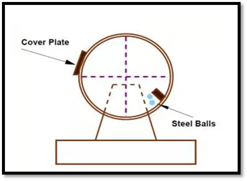
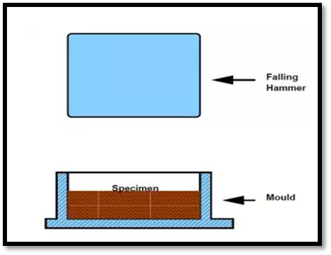
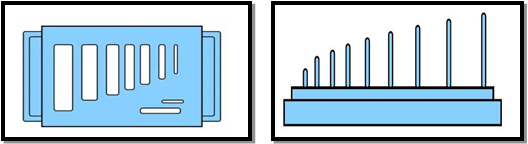
    Fig.3: Flakiness and Elongation Test
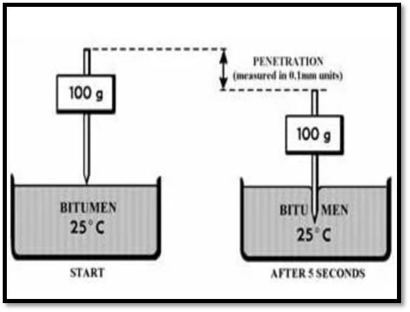
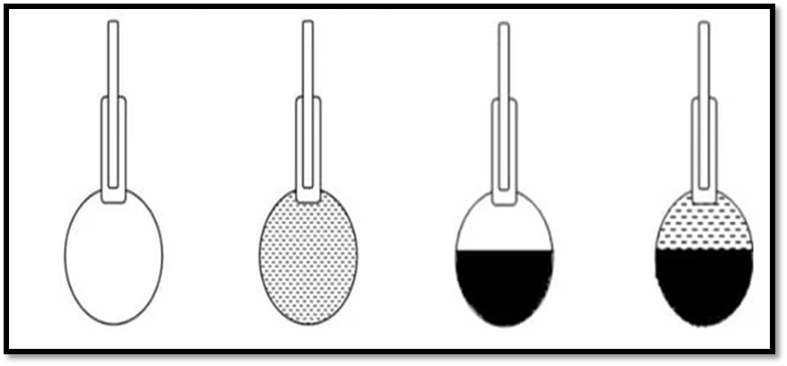
     

    6.  Specific Gravity Test

  • Specific gravity of an aggregate is the ratio of its mass to that of an equal volume of distilled water at specific temperature. The specific gravity of aggregate is of two types.
  • Bulk specific gravity, in which total volume of aggregates along with their void space is considered. Apparent specific gravity, in which the volume of aggregates without considering void spaces is taken into account.
  • The specific gravity of aggregates normally used in road construction ranges from about 2.5 to 2.9.
  • 7.  Water Absorption Test

  • This test helps to determine the water absorption value of aggregate.
  • To perform this test minimum 2 kg sample should be used. The sample should be cleaned and dried.
  • Place the sample in wire basket and dip the basket in distilled water bath. To release the air between aggregates just lift and dip the basket for about 25 times in 25 seconds.
  • Leave the basket for 24 hours and after that allowed it to drain for few minutes. Aggregates should be taken on dry cloth and exposed them to atmosphere sunlight.
  • After drying, weigh the aggregates W1. Then place the aggregate in oven at 100-110oc for 24 hrs. After oven drying again weight the aggregate W2.
  • Water absorption values ranges from 0.1 to about 2.0 percent for aggregates normally used in road surfacing.
  •  

    8.  Bitumen Adhesion Test

  • Bitumen adhesion test will give the stripping of bitumen from the aggregate. In case of bitumen pavement, the bitumen should be in pure contact with aggregate.
  • To attain this aggregate should be clean and dry.
  • To determine the stripping value of bitumen static immersion test is conducted on aggregates.
  • In this test the aggregates are coated with bitumen and dried. After drying they are immersed in water at 40°c for about 24 hours.
  • Stripping value of aggregate should not exceed 5%.
  •  

    4.3.2 BINDING MATERIAL TESTS

    1.  Penetration Test

  • The penetration value of bitumen is measured by distance in tenths of mm that a standard needle would penetrate vertically into bitumen sample under standard conditions of test.
  • By this test we can determine the hardness or softness value of bitumen.
  • In this test, firstly heat the bitumen above its softening point and pour it into a container of depth attest 15mm.
  • Bitumen should be stirred wisely to remove air bubbles. Then cool it to room temperature for 90 minutes and then placed it in water bath for 90 minutes.
  • Then place the container in penetration machine adjust the needle to make contact with surface of sample. Make dial reading zero and release the needle for exactly 5 seconds and note down the penetration value of needle for that 5 seconds.
  • Just repeat the procedure thrice and note down the average value.
  • Fig.4: Penetration Test


    2. Ductility Test

  • The property of bitumen which allows it to undergo deformation or elongation is called ductility of bitumen.
  • The ductility of bitumen is measured by the distance in Cm (centimeter), to which the bitumen sample will elongate before breaking when it is pulled by standard specimen at specified speed and temperature.
  • Firstly, the bitumen sample is heated to 75-100°C and melted completely. This is poured into the assembled mold which is placed on brass plate. To prevent sticking the mold and plate are coated with glycerin and dextrin.
  • After filling the mold, placed it in room temperature for 30-40 minutes and then placed it in water for 30 minutes.
  • Then take it out and cut the excess amount of bitumen with the help of hot knife and level the surface. Then place the whole assembly in water bath of ductility machine for 85 to 95 minutes. Then detach the brass plate and the hooks of mold are fixed to machine and operate the machine.
  • The machine pulls the two clips of the mold horizontally and then bitumen elongates. The distance up to the point of breaking from the starting point is noted as ductility value of bitumen.
  • The minimum value should be 75cm.
  • Fig.5: Ductility Test


    3.  Softening Point Test

  • Softening point of bitumen indicates the point at which bitumen attains a particular degree of softening under specified conditions of the test.
  • Take small amount of bitumen sample and heat it up to 75-100oC.
  • Ring and ball apparatus is used to conduct this test.
  • Heat the rings and apply glycerin to prevent from sticking. Fill this rings with bitumen and remove the excess material with hot sharp knife.
  • Assemble the apparatus parts, balls are arranged in guided position that is on the top of bitumen sample. And fill the beaker with boiled distilled water. Then apply temperature @ 5°C per minute.
  • At certain temperature bitumen softens and ball slowly move downwards and touches the bottom plate, this point is noted as softening point.
  • Fig.6: Softening Point Test


    4.  Specific Gravity Test

  • Specific gravity of bitumen is the ratio of mass of given volume of bitumen to the mass of equal volume of water at specified temperature.
  • Specific gravity is the good indicator of quality of binder.
  • It can be determined by pycnometer method.
  • In this method, take clean and dry specific gravity bottle and take its weight(W1)
  • In the 2nd case, fill the bottle with distilled water and dip it in water bath for 30 minutes and note down the weight (W2).
  • Next, fill half the bottle with bitumen sample and weigh (W3).
  • Finally fill the bottle with half water and half portion with bitumen and weigh (W4). Now we can find out specific gravity from the formulae.
  •  


    Fig.7: Pycnometer


    5.   Viscosity Test

  • Viscosity is the property of bitumen which influences the ability of bitumen to spread, penetrate into the voids and also coat the aggregates. That is, it influences the fluid property of bitumen.
  • If viscosity of bitumen is higher, compactive effort of bitumen reduces and heterogeneous mixture arises.
  • If viscosity is lower, then it will lubricate the aggregate particles.
  • Viscosity is determined by using tar viscometer.
  • The viscosity of bitumen is expressed in seconds is the time required for the 50 ml bitumen sample to pass through the orifice of a cup, under standard conditions of test and at specified temperature.
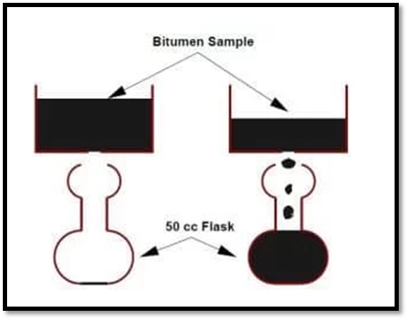
  • Fig.8: Viscosity Test

    6. Flash and Fire Point Test

  • Flash point of bitumen is defined as the point of lowest temperature at which bitumen catches vapors of test flame and fires in the form of flash.
  • Fire point of bitumen is defined as the point of lowest temperature at which the bitumen ignites and burns at least for 5 second under specific conditions of test.
  • Flash and fire point test helps to control fire accidents in bitumen coated areas.
  • By this test we can decide the bitumen grade with respect to temperature for particular areas of high temperatures.
  •  

    7.  Float Test

  • Float test is used to determine the consistency of bitumen. But we generally use penetration test and viscosity test to find out the consistency of bitumen except for certain range of consistencies.
  • The float test apparatus consists of aluminum float and brass collars.
  • These collars are filled with melted bitumen sample and cooled to 5°C and then attached them into aluminum floats and this assembly is placed in water bath at a temperature of 50°C.
  • Note down the time in seconds from the instant the float is put on the water bath until the water breaks the material and enters the float.
  •  

    8. Water Content Test

  • When bitumen is heated above the boiling point of water, sometimes foaming of bitumen occurs. To prevent this bitumen should have minimum water content in it.
  • Water content in bitumen is determined by dean and stark method.
  • In this method, the bitumen sample is kept in 500ml heat resistant glass container.
  • Container is heated to just above the boiling point of water.
  • The evaporated water is condensed and collected. This collected water is expressed in terms of mass percentage of sample.
  • It should not more than 0.2% by weight.
  •  

    9.  Loss on Heating Test

  • When the bitumen is heated, water content present in the bitumen is evaporated and bitumen becomes brittle which can be damaged easily. So, to know the amount of loss ness we will perform this test.
  • In this test, take the bitumen sample and note down its weight to 0.01gm accuracy at room temperature.
  • Then place the sample in oven and heat it for 5 hours at 163°C.
  • After that take out the sample and cool it to room temperature and take the weight to 0.01gm accuracy and note down the value. Then for the two values of weight before and after heating we can compute the loss of mass.
  • The loss should be less than 5% of total weight otherwise it is not preferred for construction.
  •  

    Key Takeaways:

  • Water Bound Macadam: - Water bound macadam road is a road in which the wearing course consists of clean crushed aggregates which are mechanically interlocked by rolling. 
  • Consistency of Bitumen: - The consistency of bitumen is measure of its susceptibility to temperature change and resistance to flow which affects ability and resistance to deformation of the mixture.
  •  


    4.4 Design of Highway Pavement

    4.4.1 Types of Pavements

    The pavements can be classified based on the structural performance into two, flexible pavements and rigid pavements.

    In flexible pavements, wheel loads are transferred by grain-to-grain contact of the aggregate through the granular structure.

    The flexible pavement, having less flexural strength, acts like a flexible sheet (e.g. bituminous road).

    In rigid pavements, wheel loads are transferred to sub-grade soil by flexural strength of the pavement and the pavement acts like a rigid plate (e.g. cement concrete roads).

    In addition to these, composite pavements are also available.

    A thin layer of flexible pavement over rigid pavement is an ideal pavement with most desirable characteristics. However, such pavements are rarely used in new construction because of high cost and complex analysis required.

    1 Flexible Pavements

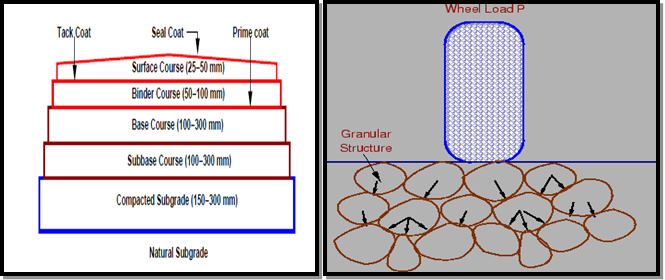
    Fig.9: Flexible Pavement


    A flexible pavement invariably consists of all the courses as shown in Fig 9. Thus, it is a multi-layered system with low flexural strength.

    The external loads are largely transmitted to the subgrade through the intervening layers-the base and the sub-base – by means of interlocking at the grain-to-grain contacts in the granular structure.

    Lateral distribution of the compressive stresses on to a larger area with increasing depth is the basic mechanism of stress transfer.

    The thicknesses of the intervening courses are so designed as to keep the stresses transferred to the subgrade soil less than the allowable bearing pressure to ensure that deformations or settlements remain within permissible limits.

    The load distribution capacity of each of these layers depends upon the nature of the materials and the mix design aspects.

    The top layer or the surface (or wearing) course, which is in direct contact with the traffic loads has to be necessarily the strongest, while the layers below can be of relatively lower strength.

    The surface course, therefore, consists of a mix with a binder material like bitumen and mineral aggregates. The base and sub-base courses consists of granular materials like crushed stone aggregate, gravel and aggregate-soil mixes.

    The base and sub-base courses may consist of more than one layer of slightly different materials and specifications. Another important characteristic of a flexible pavement is that the deformations (especially if excessive) of the subgrade are transmitted and reflected to the surface and vice versa; that is why it needs a strong subgrade for successful performance.

    2. Types of Flexible Pavements

    The following types of construction have been used in flexible pavement:

  • Conventional Layered Flexible Pavement,
  • Full - Depth Asphalt Pavement, And
  • Contained Rock Asphalt Mat (CRAM).
  • Conventional Flexible Pavements 
  • These are layered systems with high quality expensive materials are placed in the top where stresses are highand low quality cheap materials are placed in lower layers.

  • Full - Depth Asphalt Pavements 
  • These are constructed by placing bituminous layers directly on the soil sub-grade. This is more suitable when there is high traffic and local materials are not available.

  • Contained Rock Asphalt Mats 
  • These are constructed by placing dense/open graded aggregate layers in between two asphalt layers.

    Modified dense graded asphalt concrete is placed above the sub-grade will significantly reduce the vertical compressive strain on soil sub-grade and protect from surface water.

    3. Rigid Pavements

  • A rigid pavement, in contrast to a flexible one, derives its capacity to resist loads by virtue of its flexural strength.
  • Flexural strength allows the pavement to bridge over minor irregularities or weak spots in the subgrade or other courses such as the base or sub-base upon which it rests. Thus, the inherent strength of the pavement slab itself plays a major role in resisting the wheel loads; this, however, cannot under-rate the need for a strong subgrade.
  • It simply means that, provided a certain minimum support is derived from the subgrade, the performance of the rigid pavement is governed by the strength of the pavement slab rather than by that of the subgrade. Rigid pavements consist of cement concrete (OPC), which may be plain, reinforced or pre-stressed concrete.
  • The primary difference between a rigid pavement and a flexible one is in the structural behavior; the critical condition of stress is the maximum flexural stress in the pavement slab not only due to the wheel load, but also due to warping caused by changes in temperature in the summer and winter seasons, and during the day and night. The warping of the slab is caused by the temperature gradient between the top and bottom, and the consequent flexure.
  • Further, temperature changes tend to cause stresses due to friction at the interface between the slab and the layer below, which opposes the movement of the slab.
  • A rigid pavement can serve the dual purpose of a base and a wearing course. However, it is not normally laid directly over the subgrade when the latter consists of fine-grained soil.
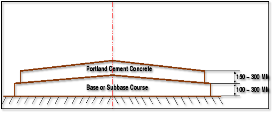
  •                     Fig.10:  Typical Cross section of Rigid pavement


    1. Types of Rigid Pavements

    Rigid pavements can be classified into four types:

  • Jointed Plain Concrete Pavement (JPCP).
  • Jointed Reinforced Concrete Pavement (JRCP).
  • Continuous Reinforced Concrete Pavement (CRCP).
  • Pre-Stressed Concrete Pavement (PCP).
  • Jointed Plain Concrete Pavement:
  • Because of their cost-effectiveness and reliability, the vast majority of concrete pavements constructed today are JPCP designs.
  • They do not contain reinforcement.
  • They have transverse joints generally spaced less than 5 to 6.5 m apart.
  • They may contain dowel bars across the transverse joints to transfer traffic loads across slabs and may contain tie bars across longitudinal joints to promote aggregate interlock between slabs.
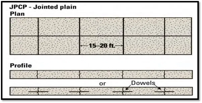
  • Fig.11: Jointed Plain Concrete Pavement


  • Jointed Reinforced Concrete Pavement:
  • Although reinforcements do not improve the structural capacity significantly, they can drastically increase the joint spacing to 10 to 30m.
  • Dowel bars are required for load transfer.
  • Reinforcement’s help to keep the slab together even after cracks.
  • The reinforcement, distributed throughout the slab, composes about 0.15 to 0.25 percent of the cross-sectional area and is designed to hold tightly together any transverse cracks that develop in the slab.
  • It is difficult to ensure that joints are cut where the rein­forcement has been discontinued.
  • This pavement type is not as common as it once was on State highways, but it is used to some extent by municipalities.
  •  

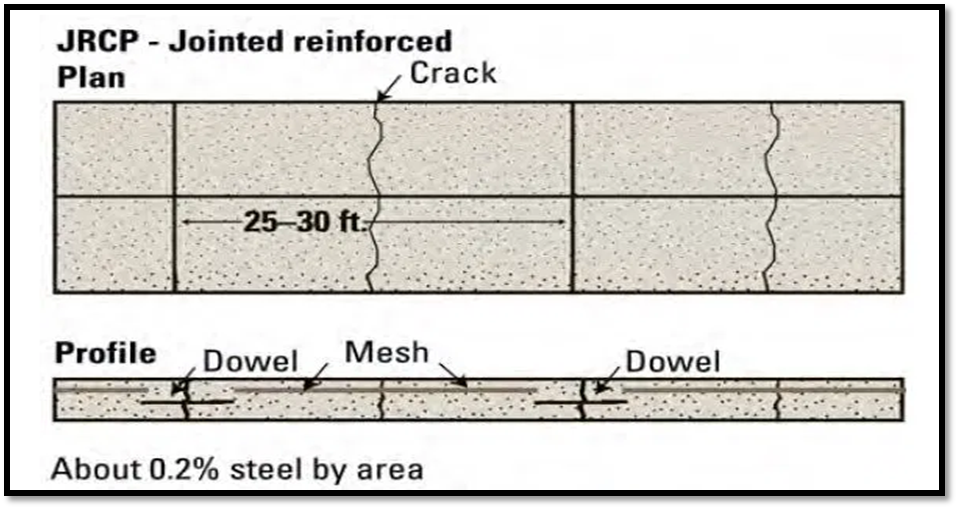
    Fig.12: Jointed Reinforced Concrete Pavement


  • Continuous Reinforced Concrete Pavement:
    • CRCP designs have no transverse joints, but contain a significant amount of longitudinal rein­forcement, typically 0.6 to 0.8 percent of the cross-sectional area.
    • Transverse reinforcement is often used.
    • The high content of reinforcement both influences the development of transverse cracks within an acceptable spacing (about 0.9 to 2.5 m apart) and serves to hold cracks tightly together.
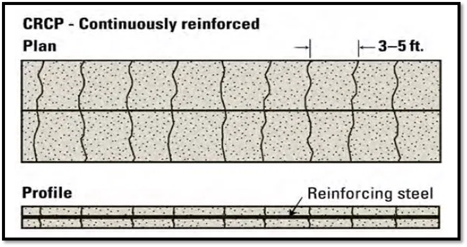
  • Fig.13: Continuous Reinforced Concrete Pavement

    3. Semi-Rigid Pavements:

  • A semi-rigid pavement is intermediate between the flexible and the rigid types.
  • In this type, a base course of lean cement concrete, soil-cement (soil mixed with cement for a binder), or lime-pozzolona concrete (lime-fly ash-aggregate mix) is provided.
  • A suitable surface course is provided as in a flexible pavement. The semi-rigid pavement derives some flexural strength, but much less than that of a cement concrete pavement; however, the phenomenon of lateral distribution of loads through the pavement depth, provides support.
  • Under certain circumstances of traffic and availability of materials, a semi-rigid type of pavement may prove to be economical.
  • 4. Composite Pavements:

  • A composite pavement comprises multiple, structurally different layers of heterogeneous nature. A typical example is a concrete pavement of two layers, sandwiching a brick layer. A base of roller compacted concrete and surface course of bitumen is another example.
  • Pavements of bricks, stone blocks, and precast cement concrete blocks laid over granular bases may also be considered to come under this category.
  • Low-cost roads, in our country, consist of roads constructed primarily with soil using stabilization techniques. From the structural point of view, it is of the flexible type. Loosely, a road with at least one stone-aggregate course may be said to be a paved one.
  • If no bituminous or concrete wearing course is provided over the granular soil or aggregate course, it is said to be an unsurfaced road.
  •  

    5. Comparison between Flexible Pavements and Rigid Pavements

    Sr. No.

    Flexible Pavement

    Rigid Pavement

    1.

    It consists of a series of layers with the highest quality materials at or near the surface of pavement.

    It consists of one layer Portland cement concrete slab or relatively high flexural strength.

    2.

    It reflects the deformations of subgrade and subsequent layers on the surface.

    It is able to bridge over localized failures and area of inadequate support.

    3.

    Its stability depends upon the aggregate interlock, particle friction and cohesion.

    Its structural strength is provided by the pavement slab itself by its beam action.

    4.

    Pavement design is greatly influenced by the subgrade strength.

    Flexural strength of concrete is a major factor for design.

    5.

    It functions by a way of load distribution through the component layers

    It distributes load over a wide area of subgrade because of its rigidity and high modulus of elasticity.

    6.

    Temperature variations due to change in atmospheric conditions do not produce stresses in flexible pavements.

    Temperature changes induce heavy stresses in rigid pavements.

    7.

    Flexible pavements have self-healing properties due to heavier wheel loads are recoverable due to some extent.

    Any excessive deformations occurring due to heavier wheel loads are not recoverable, i.e. settlements are permanent.


    Sr. No.

    Flexible Pavement

    Rigid Pavement

    8.

    The earthen, gravel, water bound macadam and bituminous roads are known as flexible pavement.

    Cement concrete roads are known as rigid pavement.

    9.

    In flexible pavement, the top surface takes to shape of the sub surface soil.

    The rigid pavement has more stiffness and capacity to bridge over loose soil pockets in the sub grade.

    10.

    Due to more stiffness and thickness, there are no ups and downs on concrete roads.

    Due to flexibility, there are ups and downs on WBM roads and bituminous roads, but there is no ups and down in case of rigid pavement.

    11.

    Design principle based on load distribution characteristics of the components.

    Designed and analyzed by using the elastic theory.

    12.

    Granular material is used in flexible pavement.

    Cement concrete either plain reinforced or pre stressed concrete is used in rigid pavement.

    13.

    It has low or negligible flexural strength.

    It is associated with rigidity or flexural strength or slab action so the load is distributed over a wide area of sub-grade soil.

    14.

    Elastic deformation due to normal loading.

    Acts as a beam or cantilever for normal loading.

    15.

    Local depression due to excessive loading.

    Causes cracks due to excessive loading.

    16.

    Transmits vertical and compressive stresses to the lower layer.

    Tensile stress and temperature stress increase.

    17.

    It is constructed in the number of layers in design practice.

    It is laid in slabs with steel reinforcement in design practice.

    18.

    Road can be used for traffic within 24 hours.

    Road cannot e used until 14 days of curing.

    19.

    Rolling of the surfacing is required.

    Rolling of the surfacing is not required.

    20.

    Initial cost is low.

    Initial cost is high.

    21.

    Life span is short.

    Life span is long.

    22.

    Their thickness is more.

    Their thickness is less.


    Key Takeaways:

  • Sub-Base and Base course: - It helps in transferring the load from top to bottom and ensure proper drainage.
  • Surface Course: - It is the top most layer of the pavement. It provides smooth rising surface and takes wear and tear.
  • Rutting: - It is consolidation of one or more layer of the pavement.
  • Fatigue: - It is repeated number of axle load.
  •  

    4.4.2 Design factors

    There are many factors that affect pavement design which can be classified into four categories as traffic and loading, structural models, material characterization, environment.

    4.4.2.1 Traffic and loading

    Traffic is the most important factor in the pavement design. The key factors include contact pressure, wheel load, axle configuration, moving loads, load, and load repetitions.

    1. Contact pressure: The tyre pressure is an important factor, as it determines the contact area and the contact pressure between the wheel and the pavement surface. Even though the shape of the contact area is elliptical, for sake of simplicity in analysis, a circular area is often considered.

    2. Wheel load: The next important factor is the wheel load which determines the depth of the pavement required to ensure that the Subgrade soil is not failed. Wheel configuration affects the stress distribution and deflection within a pavement. Many commercial vehicles have dual rear wheels which ensure that the contact pressure is within the limits. The normal practice is to convert dual wheel into an equivalent single wheel load so that the analysis is made simpler.

    3. Axle configuration: The load carrying capacity of the commercial vehicle is further enhanced by the introduction of multiple axles.

    4. Moving loads: The damage to the pavement is much higher if the vehicle is moving at creep speed. Many studies show that when the speed is increased from 2 km/hr to 24 km/hr, the stresses and deflection reduced by 40 per cent.

    5. Repetition of Loads: The influences of traffic on pavement not only depend on the magnitude of the wheel load, but also on the frequency of the load applications. Each load application causes some deformation and the total deformation is the summation of all these. Although the pavement deformation due to single axle load is very small, the cumulative effect of number of load repetition is significant. Therefore, modern design is based on total number of standard axle load (usually 80 kN single axle).

    6. Layered elastic model: A layered elastic model can compute stresses, strains, and deflections at any point in a pavement structure resulting from the application of a surface load.

    7. Temperature: The effect of temperature on asphalt pavements is different from that of concrete pavements. Temperature affects the resilient modulus of asphalt layers, while it induces curling of concrete slab. In rigid pavements, due to difference in temperatures of top and bottom of slab, temperature stresses or frictional stresses are developed.

    8. Precipitation: The precipitation from rain and snow affects the quantity of surface water infiltrating into the Subgrade and the depth of ground water table. Poor drainage may bring lack of shear strength, pumping, loss of support, etc.


    Key Takeaways:

  • Axle load: - The axle load of a wheeled vehicle is the total weight bearing on the roadway for all wheels connected to a given axle.
  • Contact Pressure: - The contact pressure is the ratio of the normal load to the true contact area, which is the sum of the front and rear areas.
  • Tyre Pressure: - Tyre pressure is a measurement of how much air is in your pneumatic tyre, and ensures the tyres wear evenly and maintain the correct level of grip on the road.
  • 4.4.3 Design of bituminous paving mixes

    A bituminous mix is defined as a mixture of coarse aggregates, fine aggregates, filler and binder in order to produce a mix with desirable properties like workability, strength, durability and economic considerations.

    The objective of the mix design is to produce a bituminous mix with the following properties:

  • Higher durability of the pavement surface
  • Sufficient strength to resist shear deformation under varying traffic load
  • Sufficient number of air voids in the compacted bitumen so as to allow additional compaction by traffic loads
  • High workability to allow easy placement without segregation
  • Sufficient flexibility so as to avoid premature cracking due to varying temperature and traffic loads
  • Three design methods for mix are available:

  • Marshall Method
  • Modified Hubbard-field Method
  • Hveem Method
  • Today, the Marshall method is considered to be the standard method of bituminous mix design. It is therefore discussed in detail below.

    4.4.3.1 Constituents of a mix

  • Coarse aggregates: provide compressive strength, shear strength and good interlocking properties to the mix (Example: Granite)
  • Fine aggregates: fill the voids between the coarse aggregate and stiffen the binder (Example: Sand, Rock dust)
  • Filler: fills voids, stiffens binder and increases the permeability of the mix (Example: Rock dust, cement, lime)
  • Binder: Fills voids and imparts adhesiveness & impermeability to the mix (Example: Bitumen, Asphalt, Tar)
  • 4.4.3.2 Types of mix

  • Well-graded mix: It has a good proportion of all constituents and offers good compressive strength and some tensile strength to the mix. It is adense mix and is also known as bituminous concrete.
  • Gap-graded mix: Few large coarse aggregates are missing from the mix but it has good fatigue and tensile strength.
  • Open-graded mix: Fine aggregate and filler are missing from the mix. It is porous and offers good friction It also has low strength.
  • Unbounded: Binder is absent in the mix. Under loads, it behaves as if its components are not linked together even though good interlocking exists. It has very low tensile strength and requires kerb protection.
  • 4.4.3.3 Design of bituminous mixes

    1. Selection of Aggregate

  • Crushed aggregates and sharp sands produce higher stability of the mix when compared with gravel and rounded sands.
  • In base course, aggregates of size 2.5 to 5 cm are used whereas in surface course, 1.25 to 1.87 cm size aggregates are used.
  • Binder content is 5 to 7.5% by weight of mix.
  • 2. Determination of Specific Gravity

    The average specific gravity Gm of the blended aggregate mix is calculated from the equation:

    Gm =

    Here, W1, W2, W3, W4 are % by weight of aggregates and G1, G2, G3, G4 are their respective specific gravity.

    3. Bulk specific gravity of mix Gm

    The bulk specific gravity or the actual specific gravity of the mix Gm is the specific gravity considering air voids and is found out by:

                                                            Gm =

    Where, Wm is the weight of mix in air, Ww is the weight of mix in water, Note that gives the volume of the mix. Sometimes to get accurate bulk specific gravity, the specimen is coated with thin film of paraffin wax, when weight is taken in the water. This however requires considering the weight and volume of wax in the calculations.

    4. Air voids percent Vv

    Air voids Vv is the percent of air voids by volume in the specimen and is given by:

                                                           Vv = X 100

    Where, Gt is the theoretical specific gravity of the mix, and Gm is the bulk or actual specific gravity of the mix.

    5. Percent volume of bitumen Vb

    The volume of bitumen Vb is the percent of volume of bitumen to the total volume and given by:

                                                              Vb =

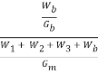
    Where, W1 is the weight of coarse aggregate in the total mix, W2 is the weight of fine aggregate in the total mix, W3 is the weight of filler in the total mix, Wb is the weight of bitumen in the total mix, Gb is the apparent specific gravity of bitumen, and Gm is the bulk specific gravity of mix.

    6. Voids in mineral aggregate VMA

    Voids in mineral aggregate VMA is the volume of voids in the aggregates, and is the sum of air voids and volume of bitumen, and is calculated from

                                                              VMA = Vv + Vb

    Where, Vv is the percent air voids in the mix. And Vb is percent bitumen content in the mix.

    7. Voids filled with bitumen VFB

    Voids filled with bitumen VFB is the voids in the mineral aggregate frame work filled with the bitumen, and is calculated as:

                                                             VFB=
    Where, Vb is percent bitumen content in the mix. And VMA is the percent voids in the mineral aggregate

    4.4.3.4 Marshall Method of Bituminous Mix Design

    Marshall Mix Design method involves selecting the bitumen binder content of a suitable density that satisfies minimum stability and range of flow values.

    Marshall Stability of a test specimen is defined as the maximum load that produces failure when the specimen is pre-heated to a prescribed temperature and load is applied at a constant strain rate of 5 cm per minute. Simultaneously, a dial gauge is used to measure the vertical deformation of the specimen. Deformation value of 0.25 mm is called the Marshall Flow Value of the specimen.

    Steps in Marshall Mix Design

    Step 1: Determine the physical properties, size and gradation of aggregates.

    Step 2: Select the type of asphalt/ bitumen binder.

    Step 3: Prepare initial samples, each with different bitumen binder content.

    Step 4: Average value of various properties are determined for each mix and the following graphical plots are prepared:

  • Bitumen binder content vs. Density
  • Bitumen binder content vs. Marshall stability
  • Bitumen binder content vs. Flow
  • Bitumen binder content vs. air voids
  • Bitumen binder content vs. voids in mineral aggregates (VMA)
  • Bitumen binder content vs. voids filled with asphalt (VFA)
  • Step 5: Determine the optimum bitumen content for the mix design by taking average value of the following three bitumen contents found form the graphs obtained in the previous step:

  • Binder content corresponding to maximum stability
  • Binder content corresponding to maximum bulk specific gravity 
  • Binder content corresponding to the to the air void content of 4 percent
  • Step 6: Compare each of these values against design requirements and if all comply with design requirements, then the selected bitumen content is acceptable. Otherwise, redesign the mixture.


    Key Takeaways:


  • Marshall Stability: - Marshall Stability of a test specimen is the maximum load required to produce failure when the specimen is preheated to a prescribed temperature placed in a special test head and the load is applied at a constant strain (5 cm per minute).
  • Flow Value: - The deformation at failure point expressed in units of 0.25 mm.
  •  

    4.4.4 Design of Flexible Pavement by CBR method (IRC: 37- Latest revision)

    4.4.4.1 California Bearing Ratio (C.B.R.) Test

  • The California Bearing Ratio(CBR) test is a measure of resistance of a material to penetration of standard plunger under controlled density and moisture conditions.
  • It was developed by the California Division of Highways as a method of classifying and evaluating soil- subgrade and base course materials for flexible pavements.
  • CBR test may be conducted in remolded or undisturbed sample. Test consists of causing a cylindrical plunger of 50mm diameter to penetrate a pavement component material at 1.25mm/minute.
  • The loads for 2.5mm and 5mm are recorded. This load is expressed as a percentage of standard load value at a respective deformation level to obtain CBR value.
  • The aim of this test is the determination of California Bearing Ratio value of the subgrade soil.
  • 4.4.4.2 Procedure of California Bearing Ratio Test

  • Sieve the sample through 20mm IS sieve. Take 5 kg of the sample of soil specimen. Add water to the soil in the quantity such that optimum moisture content or field moisture content is reached.
  • Then soil and water are mixed thoroughly. Spacer disc is placed over the base plate at the bottom of mould and a coarse filter paper is placed over the spacer disc.
  • The prepared soil water mix is divided into five. The mould is cleaned and oil is applied. Then fill one fifth of the mould with the prepared soil. That layer is compacted by giving 56 evenly distributed blows using a hammer of weight 4.89kg.
  • The top layer of the compacted soil is scratched. Again second layer is filled and process is repeated. After 3rd layer, collar is also attached to the mould and process is continued.
  • After fifth layer collar is removed and excess soil is struck off. Remove base plate and invert the mould. Then it is clamped to baseplate.
  • Surcharge weights of 2.5kg are placed on top surface of soil. Mould containing specimen is placed in position on the testing machine.
  • The penetration plunger is brought in contact with the soil and a load of 4kg (seating load) is applied so that contact between soil and plunger is established. Then dial readings are adjusted to zero.
  • Load is applied such that penetration rate is 1.25mm per minute. Load at penetration of 0.5, 1, 1.5, 2, 2.5, 3, 4, 5, 7.5, 10 and 12.5mm are noted.
  • Two values of CBR will be obtained. If the value of 2.5 mm is greater than that of 5.0 mm penetration, the former is adopted.
  • If the CBR value obtained from test at 5.0 mm penetration is higher than that at 2.5 mm, then the test is to be repeated for checking. If the check test again gives similar results, then higher value obtained at 5.0 mm penetration is reported as the CBR value.
  • The average CBR value of three test specimens is reported as the CBR value of the sample.
  •                 CBR (%) = 100

                   CBR(2.5mm) = X 100

                   CBR(5.0mm) = X 100

                  CBR = Higher of CBR2.5 mm/ CBR5.0 mm

    Standard Load (2.5 mm Penetration) = 1370 Kg

    Standard pressure/stress @ 2.5 mm =

                                                               = 70 Kg/cm2

    Standard pressure/stress @ 5.0 mm =

                                                               = 105 Kg/cm2

    CBR of a soil sample is average of CBR of three specimen prepared from same sample.

    Generally, 2.5 mm CBR is more than 5 mm CBR. But if 5 mm CBR is more than 2.5 mm CBR, than test must be repReated again and again. If same result comes then higher value is considered as CBR i.e., CBR @ 5 mm.

    Empirical formula for thickness, (T)cm=

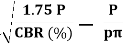
    (Applicable for CBR>12%)

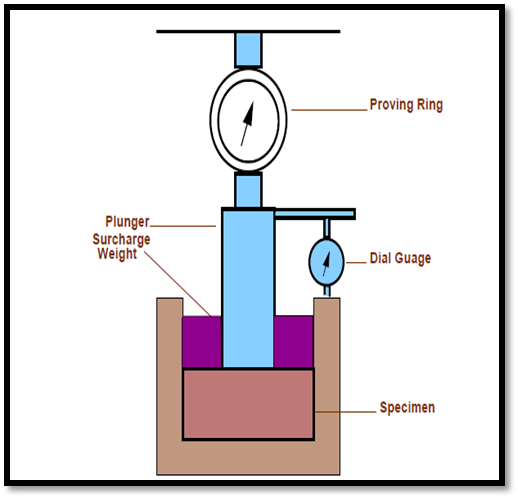
    Fig.14: California Bearing Ratio Test


    Key Takeaways:

  • Rigidity Factor: - It is defined as the ratio of contact pressure by tyre pressure.
  • Equivalent Single Wheel Load: -It is a load applied on single tyre which will be having equivalent number of parameters such as stress, strain, and deflection.
  • 4.4.5 Design of rigid pavement

    A rigid pavement, in contrast to a flexible one, derives its capacity to resist loads by virtue of its flexural strength.

    Flexural strength allows the pavement to bridge over minor irregularities or weak spots in the subgrade or other courses such as the base or sub-base upon which it rests. Thus, the inherent strength of the pavement slab itself plays a major role in resisting the wheel loads; this, however, cannot under-rate the need for a strong subgrade.

    It simply means that, provided a certain minimum support is derived from the subgrade, the performance of the rigid pavement is governed by the strength of the pavement slab rather than by that of the subgrade. Rigid pavements consist of cement concrete (OPC), which may be plain, reinforced or pre-stressed concrete.

    The primary difference between a rigid pavement and a flexible one is in the structural behavior; the critical condition of stress is the maximum flexural stress in the pavement slab not only due to the wheel load, but also due to warping caused by changes in temperature in the summer and winter seasons, and during the day and night. The warping of the slab is caused by the temperature gradient between the top and bottom, and the consequent flexure.

    Further, temperature changes tend to cause stresses due to friction at the interface between the slab and the layer below, which opposes the movement of the slab.

    A rigid pavement can serve the dual purpose of a base and a wearing course. However, it is not normally laid directly over the subgrade when the latter consists of fine-grained soil.

    Providing a base or a sub-base below the pavement can enhance the life of the pavement significantly, and may prove economical in the long run.

    \begin{figure}\centerline{\epsfig{file=p04-rigid-pavement-cross-section,width=15cm}}\end{figure}

    Fig.15: Typical Cross section of Rigid pavement

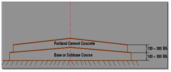
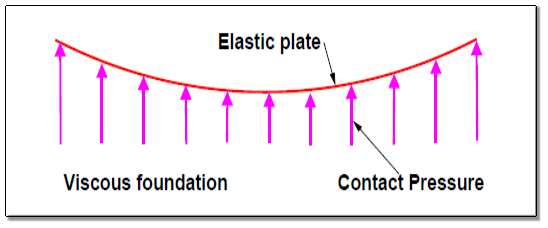
    Fig.16: Stress Distribution


    Key Takeaways:

  • Modulus of Subgrade Reaction: - It shows supporting capacity of soil Subgrade and it is calculated by performing plate bearing test.
  • Radius of Relative Stiffness: - The radius of relative stiffness is incorporated into the Westergaard analysis methods of rigid pavement design and in several subsequent methods of analysis.
  •  

    4.4.6 Westergaard theory

    The Westergaard method for rigid pavement design involves a calculation of the stresses acting in the pavement under the wheel load. This stress is then compared to the strength of the pavement slab to determine whether the slab is sufficiently strong to accommodate the proposed loadings.

  • The test site is prepared and loose material is removed so that the 75 cm diameter plate rests horizontally in full contact with the soil sub-grade.
  • The plate is seated accurately and then a seating load equivalent to a pressure of 0.07 kg/cm2 (320 kg for 75 cm diameter plate) is applied and released after a few seconds. The settlement dial gauge is now set corresponding to zero load.
  • A load is applied by means of jack, sufficient to cause an average settlement of about 0.25 cm.
  • When there is no perceptible increase in settlement or when the rate of settlement is less than 0.025 mm per minute (in the case of soils with high moisture content or in clayey soils) the load dial reading and the settlement dial readings are noted.
  • Deflection of the plate is measured by means of deflection dials; placed usually at one-third points of the plate near its outer edge.
  • To minimize bending, a series of stacked plates should be used.
  • Average of three or four settlement dial readings is taken as the settlement of the plate corresponding to the applied load. Load is then increased till the average settlement increase to a further amount of about 0.25 mm, and the load and average settlement readings are noted as before.
  • The procedure is repeated till the settlement is about 1.75 mm or more.
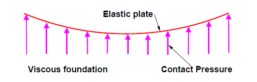
  • Fig.17: Westergaard theory

  • Calculation A graph is plotted with the mean settlement versus bearing pressure (load per unit area) as shown in Figure.
  • The pressure corresponding to a settlement is obtained from this graph.
  • The modulus of Subgrade reaction is calculated from the relation
  • Key Takeaways:

  • Frictional stresses: - Due to the contraction of slab due to shrinkage or due to drop in temperature tensile stresses are induced at the middle portion of the slab.
  • Wheel Load Stresses: - CC slab is subjected to flexural stresses due to the wheel loads.
  •  

    4.4.7 Load and temperature stresses

    4.4.7.1 Temperature stresses

    Temperature stresses are developed in cement concrete pavement due to variation in slab temperature. This is caused by (i) daily variation resulting in a temperature gradient across the thickness of the slab and (ii) seasonal variation resulting in overall change in the slab temperature. The former results in warping stresses and the later in friction stresses.

    4.4.7.2 Warping stress

    The warping stress at the interior, edge and corner regions, denoted as ti ,te , tc in kg/cm2 respectively and given by the equation

    St,i=

    St,e = Maximum of ( or

    St,c =

    Coefficient of thermal expansion = 12 X 10-6/oC

            t = temperature difference between top and bottom of the pavement.

            a = radius of contact area

         Cx & Cy = Coefficient which is based upon, ratio

                    Lx = Spacing between transverse joints

                    Ly = Spacing between longitudinal joints

    4.4.7.3 Frictional stresses

    The frictional stress of in kg/cm2 is given by the equation

    =

    Where, W is the unit weight of concrete in kg/cm2 (2400), f is the coefficient of sub grade friction (1.5) and L is the length of the slab in meters.

    4.2.7.4 Combination of stresses

    The cumulative effect of the different stress give rise to the following thee critical cases

  • Summer, mid-day: The critical stress is for edge region given by
    critical =
    e +
    te -
    f
  • Winter, mid-day: The critical combination of stress is for the edge region given by
    critical =
    e +
    te +
    f
  • Mid-nights: The critical combination of stress is for the corner region given by
    critical =
    e +
    te
  •  

    Key Takeaways:

  • Warping stress: - Warping of the pavement slab is caused by a difference in temperature between top and bottom of the slab. 
  •  

    4.4.8 Joints

    4.4.8.1 Expansion joints

    The purpose of the expansion joint is to allow the expansion of the pavement due to rise in temperature with respect to construction temperature. The design consideration is:

  • Provided along the longitudinal direction,
  • design involves finding the joint spacing for a given expansion joint thickness (say 2.5 cm specified by IRC) subjected to some maximum spacing (say 140 as per IRC)
  • PIC

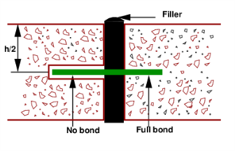
    Fig.14: Expansion Joint

    4.4.8.2 Contraction joints

    The purpose of the contraction joint is to allow the contraction of the slab due to fall in slab temperature below the construction temperature. The design considerations are:

  • The movement is restricted by the sub-grade friction
  • Design involves the length of the slab given by:
  •                                  Lc =

    Where, Sc is the allowable stress in tension in cement concrete and is taken as 0.8 kg/cm2, W is the unit weight of the concrete which can be taken as 2400 kg/cm3 and f is the coefficient of sub-grade friction which can be taken as 1.5.

  • Steel reinforcements can be use, however with a maximum spacing of 4.5 m as per IRC.
  • PIC

    Fig.15: Contraction joint

    4.4.8.3 Dowel bars

    The purpose of the dowel bar is to effectively transfer the load between two concrete slabs and to keep the two slabs in same height. The dowel bars are provided in the direction of the traffic (longitudinal). The design considerations are:

  • Mild steel rounded bars,
  • bonded on one side and free on other side
  • 1 Bradbury’s analysis

    Bradbury’s analysis gives load transfer capacity of single dowel bar in shear, bending and bearing as follows:

                                                   Ps = 0.785 d2 Fs

                                                   Pf =

                                                 Pb =

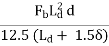
    Where, P is the load transfer capacity of a single dowel bar in shear s, bending f and bearing b, d is the diameter of the bar in cm, Ld is the length of the embedment of dowel bar in cm, δ is the joint width in cm, Fs, Ff, Fb are the permissible stress in shear, bending and bearing for the dowel bar in kg/cm2.

    2 Design procedure

    Step 1: Find the length of the dowel bar embedded in slab Ld by equating Eq. 12=Eq. 13, i.e.

    Ld = 5d

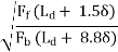
    Step 2: Find the load transfer capacities Ps, Pf, and Pb of single dowel bar with the Ld

    Step 3: Assume load capacity of dowel bar is 40 percent wheel load, find the load capacity factor f as

    Max

    Step 4: Spacing of the dowel bars.

  • Effective distance up to which effective load transfer take place is given by 1.8 l, where l is the radius of relative stiffness.
  • Assume a linear variation of capacity factor of 1.0 under load to 0 at 1.8 l.
  • Assume dowel spacing and find the capacity factor of the above spacing.
  • Actual capacity factor should be greater than the required capacity factor.
  • If not, do one more iteration with new spacing.
  • 4.4.8.4 Tie bars

    In contrast to dowel bars, tie bars are not load transfer devices, but serve as a means to tie two slabs. Hence tie bars must be deformed or hooked and must be firmly anchored into the concrete to function properly. They are smaller than dowel bars and placed at large intervals. They are provided across longitudinal joints.

    Step 1: Diameter and spacing: The diameter and the spacing is first found out by equating the total sub-grade friction to the total tensile stress for a unit length (one meter). Hence the area of steel per one meter in cm2 is given by:

                                       As X Ss = b X h X W x f

                                                    As =

    Where, b is the width of the pavement panel in m, h is the depth of the pavement in cm, W is the unit weight of the concrete (assume 2400 kg∕cm2), f is the coefficient of friction (assume 1.5), and Ss is the allowable working tensile stress in steel (assume 1750 kg∕cm2). Assume 0.8 to 1.5 cm ϕ bars for the design.


    Step 2: Length of the tie bar: Length of the tie bar is twice the length needed to develop bond stress equal to the working tensile stress and is given by:

                                                            Lt =

    Where, d is the diameter of the bar, Ss is the allowable tensile stress in kg∕cm2, and Sb is the allowable bond stress and can be assumed for plain and deformed bars respectively as 17.5 and 24.6 kg∕cm2.


    Key Takeaways:

  • Construction Joint: - This is not a joint; it is created at site due to discontinuity of work. To avoid extra joint work should always be stopped at pre defined location such as Expansion or Longitudinal joints.
  • Overlay: - Additional thickness of pavement in one or more layer is provided over existing pavement.
  •  

    4.4.9 IRC method of rigid pavement design (IRC:58-2015)  

    A part of road section from Design Ch. 2+065 to Ch. 18+000 (L=16.935 km) is used by trucks carrying wet sand mined from nearby Betwa River. The water drips down from the trucks on the pavement surface all along the road way and has damaged the pavement in the form of stripping, cracking, potholes including base course failure. Rigid pavement is proposed in this length of 16.935km as dripping of water on concrete surface will not result in “stripping”.

    In order to provide a stable construction platform and non-erodible support for PQC, a DLC sub base, 150mm thick, is included as part of the pavement structure. Similarly, a layer of relatively open graded GSB Gr-6 (as per IRC:58-2015 Table VI-I), 150mm thick above the sub grade has been considered for drainage of water to prevent excessive softening of sub grade and prevent erosion of the sub grade under adverse moisture condition.

    A separation membrane of 125 micron polyethylene is considered to be placed between PQC and DLC to reduce inter-layer friction.

    The dimensions of dowel bars & tie bars are given below:

  • Contraction joint spacing                  @ 4.5 m
  • Longitudinal joint                      @ 3.5 m width and @ 1.5 m width (tied shoulder)
  • Dowel bars 38 mm diameter plain, 500 mm long       @ 300 mm spacing
  • Tie bars 12 mm diameter deformed, 640 mm long    @ 600 mm spacing
  •  

    Key Takeaways:

  • Contraction Joint: - Contraction joints are planes, usually vertical separating concrete in a structure or a pavement placed at a designed location.
  • Longitudinal Joint: - A longitudinal joint is constructed when one lane of HMA is paved then the adjacent lane is paved next to this now cold joint.
  •  


    References:

    1. L.R. Kadiyali, Transportation Engineering, Khanna Publishing House

    2. Saxena, Subhash C, A Textbook of Highway and Traffic Engineering, CBS Publishers &

    Distributers, New Delhi

    3. Kumar, R Srinivasa, “A Text book of Highway Engineering”, Universities Press,

    Hyderabad.

    4. Kumar, R Srinivasa, “Pavement Design”, Universities Press, Hyderabad.

    5. Chakraborty Partha & Das Animesh., “Principles of Transportation Engineering”,

    Prentice Hall (India), New Delhi,

    6. IRC : 37- Latest revision, “Tentative Guidelines for the design of Flexible Pavements”

    Indian Roads Congress, New Delhi

    7. IRC:58-2015 Guidelines for the Design of Plain Jointed Rigid Pavements for Highways

    (Fourth Revision) (with CD)

    8. IRC:65-2017 Guidelines for Planning and Design of Roundabouts (First Revision)

    9. IRC:73-1980 Geometric Design Standards for Rural (Non-Urban) Highways

    10. IRC:106-1990 Guidelines for Capacity of Urban Roads in Plain Areas

    11. IRC:93-1985 Guidelines on Design and Installation of Road Traffic Signals.

    12. IRC:92-2017 Guidelines for Design of Interchanges in Urban Areas (First Revision)

    13. IRC: SP: 68-2005, “Guidelines for Construction of Roller Compacted Concrete Pavements”,

    Indian Roads Congress, New Delhi.

    14. IRC: 15-2002, “Standard Specifications and Code of Practice for construction of Concrete

    Roads” Indian Roads Congress, New Delhi.

    15. MORTH, “Specifications for Road and Bridge Works”, Ministry of Shipping, Road

    Transport & Highways, Published by Indian Roads Congress, New Delhi.


    Zoom Out
    Zoom In
    Sign Up
    0 matching results found
    Index
    Notes
    Highlighted
    Underlined
    :
    Browse by Topics
    :
    Notes
    Highlighted
    Underlined
    Loading ....