Unit - 4
PIC Interfacing-II
4.1.1Capture Mode
CCP Pin Configuration
CCP prescaler
4.1.2 Compare and PWM generation
Compare Mode
PWM Mode
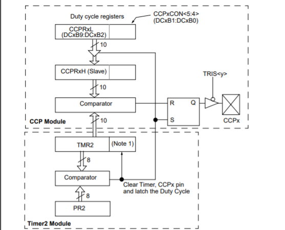
Fig.1. block diagram of the CCP module in PWM mode
PWM Period
PWM period = [(PR2) + 1] • 4 • TOSC • (TMR2 prescale value),
specified in units of time
PWM Duty Cycle
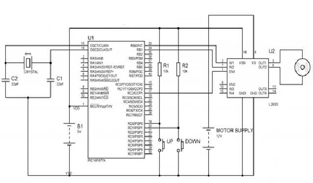
Fig.2. DC motor speed control with CPP
Key Takeaway:
4.4.1 Study of RS232:
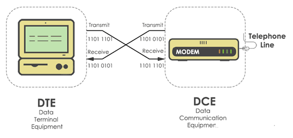
Fig.3. Study of RS232
4.4.2 12C:
4.4.3 SPI
Advantages
Disadvantages
4.4.4 UART
Advantages
Disadvantages
4.4.5 Serial communication programming using embedded C
Serial Vs Parallel
Key Takeaway:
References:
1.Peatman, John B, “Design with PIC Microcontroller”, Pearson Education PTE
2.Microchip’s PIC18FXXX Data Sheet
3.Muhammad Ali Mazidi, SarmadNaimi, “ARM Assembly Language Programming & Architecture”


