Unit - 3
PIC Interrupts & Interfacing-I
Interrupt:
Polling:
Fig.1. IVT
right parenthesis.
Fig.2. IVT
1. It finish the instruction it is executing and saves the address of the next instruction (PC) on the stack.
2. It also saves the current status of all the interrupt internally.
Key Takeaway:
3.8.1 Timer using interrupts:
Timer interrupt to blink an LED; Time delay in mode1 using interrupt method
// Use of Timer mode0 for blinking LED using interrupt method
// XTAL frequency 11.0592MHz
#include<reg51.h>
sbit LED = P1^0; //LED connected to D0 of port 1
void timer(void) interrupt 1 //interrupt no. 1 for Timer 0
{
led=~led; //toggle LED on interrupt
TH0=0xFC; // initial values loaded to timer
TL0=0x66;
}
main()
{
TMOD = 0x01; // mode1 of Timer0
TH0 = 0xFC; // initial values loaded to timer
TL0 = 0x66;
IE = 0x82; // enable interrupt
TR0 = 1; //start timer
while (1); // do nothing
}
3.8.2 External hardware interrupts

Fig.3 Bit Values of TCON
2. Setting the IT0 and IT1 bits make the external interrupt 0 and 1 edge triggered respectively.
3. By default, these bits are cleared and so external interrupt is level triggered.
4. For a level trigger interrupt, the INTx pin must remain low until the start of the ISR and should return to high before the end of ISR.
5. If the low at INTx pin goes high before the start of ISR, interrupt will not be generated.
6. Also, if the INTx pin remains low even after the end of ISR, the interrupt will be generated once again.
7. This is the reason why level trigger interrupt (low) at INTx pin must be four machine cycles long and not greater than or smaller than this.
8. Following are the steps for using external interrupt:
9. Example code
//Level trigger external interrupt
void main()
{
IE = 0x81;
while (1);
}
void ISR_ex0(void) interrupt 0
{
<body of interrupt>
}
3.8.3 Serial communication interrupts:
1. Enable the Serial Interrupt (configure the IE register).
2. Configure SCON register.
3. Write routine or function for the Serial Interrupt. The interrupt number is4.
4. Clear the RI or TI flag within the routine.
Send ‘A’ from serial port with the use of interrupt
// Sending ‘A’ through serial port with interrupt
// XTAL frequency 11.0592MHz
void main()
{
TMOD = 0x20;
TH1 = -1;
SCON = 0x50;
TR1 = 1;
IE = 0x90;
while(1);
}
void ISR_sc(void) interrupt 4
{
if(TI==1)
{
SBUF = ‘A’;
TI = 0;
}
else
RI = 0;
}
Principle behind Interfacing LED
2. The key is decoded through Column selection / Row read.
3. Write HIGH to Column One. And keep rest of the Column to LOW.
4. Scan (Read) the Row One to Row Four, to find the key.
5. Repeat until a key press (are multiple) is identified.
6. The Row pins are connected to 5,4,3 and 2nd digital IO pins of Arduino.
7. The Column pins are connected to 6,7,8 and 9th digital IO pins of Arduino.
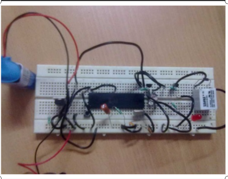
Fig.4. relay and buzzer interfacing with micro controller
Key Takeaway:
References:
1 “Electronic Devices and Circuit Theory”, Boylestad and Nashelsky, PEARSON
PUBLICATION.
2 “Electronic devices and circuits”, Salivahanan, Suresh Kumar, Vallavaraj,
TMH, 1999
3 “Integrated Electronics, Analog and Digital Circuits and Systems”, J. Millman
and Halkias, TMH, 2000
4 “Micro Electronic Circuits”, Sedra and Smith, Oxford University Press, 2000
5 “Electronic Devices and Circuits”, David A Bell, Oxford University Press, 2000


