Unit - 1
PIC Microcontroller Architecture
1.1.1 Microcontroller:
A typical microcontroller includes a processor, memory and input/output (I/O) peripherals on a single chip.”
1.1.2 History:
1.1.3 Microprocessor and Microcontroller:
Microcontroller:
Microprocessor:
Key Difference microprocessor and microcontroller:
1.1.4 Criteria for selection of microcontrollers:
1. Power efficiency
i) There is a trade-off between processing performance and power consumption: a device with higher processing power will consume more energy.
ii)Therefore, if your microcontroller is wireless and running on a rechargeable battery, you need to weigh sacrificing power efficiency against getting more processing power, or vice versa.
2. Temperature tolerance
i)Depending on the environment in which your microcontrollers operate, you may want devices that withstand extreme temperature.
ii)There will be a trade-off between temperature tolerance and cost.
3. Security
i)Hacking which targets IoT devices is rising, a threat that is especially relevant to microcontrollers used in automobiles.
ii) In response, microcontroller makers are implementing layers of security such as cryptography and physical security.
iii) Now, users can purchase microcontrollers that have been certified to the latest security standards or use MCUs with on-chip secure hardware.
4. Memory
i)The amount of memory (RAM and ROM) you need will depend on the programs you will be running. More programs need more random access memory (RAM).
ii)In addition, a GPU will require not only more RAM but faster read/write time as well.
Key Takeaways
1.2.1 Features and architecture
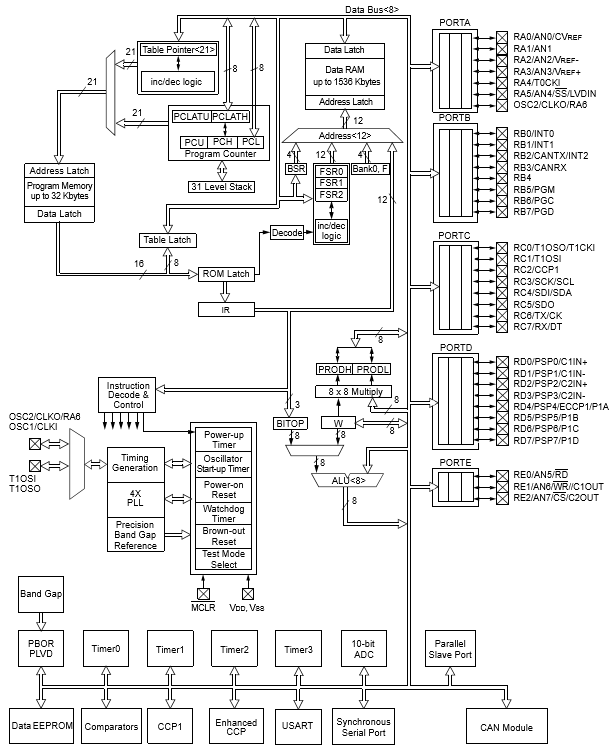
Fig.1. PIC18Fxxx Architecture
1.2.2 Comparison of PIC 18 series microcontroller:
PIC Family | No. of pins | Flash ROM | RAM | Timers | I/O pins | ADC input channel | Additional Features |
PIC10CXX | 6 | 896 Bytes | 64 Byte | 2 | 4 | 2 Channels(8 -bit Digital Result) | PWM module |
PIC12CXX | 8 | 3.5 KB | 128-256 Bytes | 2 | 6 | 3 Channels(8 -bit Digital Result) | USART,PWM module |
PIC16FXX | 14-40 | 7-28 KB | 512 Bytes-2 KB | 4 | 12 | 4 Channels(10 -bit Digital Result) | WDT,Data E,USART, I2C, SPI-EEPROM,PWM module |
PIC18FXX | 40-100 | 2MB | 32 to 128 KB | 4 | 33-72 | 12 Channels(10 -bit Digital Result) | USB,12-bit ADC,CAN,I2C,SPI Bus, USART,PWM module |
Selection
Advantages
Limitations
1.2.3 PIC18F458/452 Pin out connection
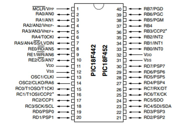
Fig.2. PIC18F442
1. PIC12F629
2. PIC12F683
3. PIC16F505
4. PIC12F508
5. PIC16F676
6 .PIC16F72
7 .PIC16F873A
8. PIC16F876A
9. PIC16F886
10. PIC16F252
1.2.4 Registers of PIC18F:
Key Takeaway:
1.3.1 Program Memory(ROM):
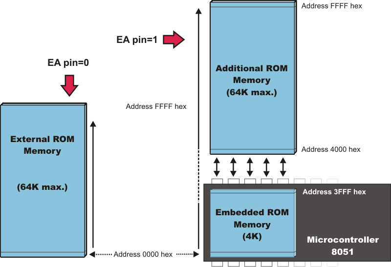
Fig.3. Program Memory
1.3.2 Data Memory(RAM):
Key Takeaway:
1.4.1 Addressing modes with instruction:
1. Addressing modes for data
2. Addressing modes for branch.
Types of addressing modes:
1. Register mode – In this type of addressing mode both the operands are registers.
Example:
MOV AX, BX
XOR AX, DX
ADD AL, BL
2. Immediate mode – In this type of addressing mode the source operand is a 8 bit or 16 bit data. Destination operand can never be immediate data.
Example:
MOV AX, 2000
MOV CL, 0A
ADD AL, 45
AND AX, 0000
3. Displacement or direct mode – In this type of addressing mode the effective address is directly given in the instruction as displacement.
Example:
MOV AX, [DISP]
MOV AX, [0500]
4. Register indirect mode – In this addressing mode the effective address is in SI, DI or BX.
Example:
MOV AX, [DI]
ADD AL, [BX]
MOV AX, [SI]
5. Based indexed mode – In this the effective address is sum of base register and index register.
Base register: BX, BP
Index register: SI, DI
6. Indexed mode – In this type of addressing mode the effective address is sum of index register and displacement.
Example:
MOV AX, [SI+2000]
MOV AL, [DI+3000]
7. Based mode – In this the effective address is the sum of base register and displacement.
Example:
MOV AL, [BP+ 0100]
8. Based indexed displacement mode – In this type of addressing mode the effective address is the sum of index register, base register and displacement.
Example:
MOV AL, [SI+BP+2000]
9. String mode – This addressing mode is related to string instructions. In this the value of SI and DI are auto incremented and decremented depending upon the value of directional flag.
Example:
MOVS B
MOVS W
10. Input/Output mode – This addressing mode is related with input output operations.
Example:
IN A, 45
OUT A, 50
11. Relative mode –In this the effective address is calculated with reference to instruction pointer.
Example:
JNZ 8 bit address
IP=IP+8 bit address
1.4.2. Oscillator configurations:
1.4.3 Reset Operation
1.4.4 Brownout Reset
1.4.5 Watchdog Timer:
- Run modes
- Idle modes
- Sleep mode
1.4.6 Power Down Modes and Configuration
Key Takeaway:
References:
1. Peatman, John B, “Design with PIC Microcontroller”, Pearson Education PTE
2. Ramesh Gaonkar, “Fundamentals of Microcontrollers and Applications In Embedded Systems (with the PIC18 Microcontroller Family)” Thomson/Delmar Learning; 1 edition (January 8, 2007), ISBN:978-1401879143
3. Microchip’s PIC18FXXX Data Sheet
4. Muhammad Ali Mazidi, SarmadNaimi, “ARM Assembly Language Programming & Architecture”


