Module IV
Electrical Machines
They convert mechanical energy into electrical energy. The energy conversion is based on the principle of production of induced emf. The construction and working are explained below.
Construction – A simple generator is shown below, the essential parts of which are
1) Yoke – It is the outer frame of machine which carries the magnetic flux produced by poles and also provides mechanical support to the poles. The yoke is generally made of cast steel or rolled steel.
2) Pole shoes – They are made up of thin lamination of anmealed steel, which are piled up under hydraulic pressure. They spread out the flux in the air gap. They reduce the reluctance as they have large cross-sectional area.
3) Held coils –They are the copper wire which are wounded around the core, the flux is produced when the current passes through these coils.
4) Armature core – It provides the low reluctance path to the flux through the armature. It carries the conductor coils and makes them to rotate, which in turn tells the magnetic flux produced. It is cylindrical in shape and made of circular steel sheets.
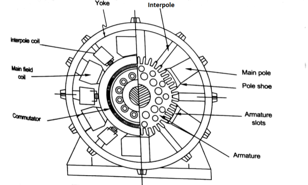
5) Armature Windings – These windings are arranged in armature slots, the slots are lined with tough insulating material. The useful EMF is encouraged in these findings and is received across brushes.
6) Commutator - It collects the current from armature and supplies to the load. It is cylindrical in shape. It periodically reverses the current direction between the rotor and external circuit. It is composed of multiple metal segments insulated from each other by thin layer of Mica. The number of segments is equal to number of armature coil.
7) Brushes and bearings - The brushes are usually made of carbon or graphite. The main function of brushes is to collect current from commutator. They are housed in brush holders and mounted on a spindle. The number of brushes per spindle depends upon the magnitude of the current to be collected from commutator.
Generating Action
The basic circuit model for a dc machine is shown below:
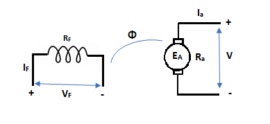
The machine operates in generating mode when the armature current is in the direction of induced emf Ea.
V = Ea – Ia Ra Ea> V
Pmech = Ea Ra = Pelect
The output power,
P0 = VIa
EaIa – VIa = Ia2 Ra
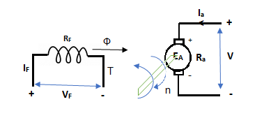
In this mode, the torque of electromagnetic origin is in opposite direction of rotation of armature.
[Pmech]gross = Shaft power = [Pmech]net + Rotational loss.
EMF Equation
The average coil emf

Wm = armature speed rad/s.
As parallel path emf is equal to armature emf,


Np = turns / parallel path = 
Z = Total armature conductors
A = Number of parallel paths.


n = armature speed rpm
Torque equation
Average conductor force
Fav = Bav l Ic
Bav = avg. Flux density over pole.
l = active conductor length.
Force, F = ZFav = BavlIcZ
T = f.r
T = Bav l IC Zr
r = mean of r gap radius.
Flux/pole = Bav
= Bav Pl
Pl


The torque is uniform for given flux/pole and armature current.
Motoring Action
In this mode, the armature current Ia flows opposite to the emf induced i.e. Ea. The basic circuit showing this mode is below:
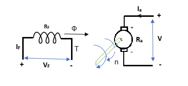
(Ea – Eb) is called as back emf here as it opposes the armature emf.
V = Ea + IaRa
Electrical power connected to mechanical form
Pelec / net = EaIa
Power input, Pi = V Ia
V Ia – EaIa = Ia2Ra = armature copper loss.
The back emf is given as
Eb = 
Types
1) Shunt motor – In this, the field winding is connected in parallel with the armature.
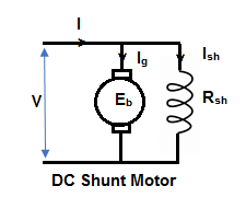
The input current I = Ia + Ish
For field winding, V = IshRsh
For armature, V = Eb + IaRa
Ia = armature current
Ish = shunt field current
V = input voltage
I = Input current
Power Input = Mechanical power + losses in armature + losses in field
VI = Pmech + Ia2Ra + Ish2Rsh
Pmech = VI – VIsh - = Ia2Ra
= V(I – Ish) – Ia2Ra
= VIa - = Ia2Rsh = (V – IaRa)Ia
Pmech = EaIa
2) Series motor – In this, the field winding is connected in series with the armature.
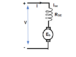
Ise = series field current
I = Ia = Ise
V = Ea + I(Ra + Rse)
VI = EaI + I2(Ra + Rse)
VI = Pmech + I2 Ra + I2Rse
Pmech = Ea I
3) Compound Motor – It is a type of dc motor which had both shunt and series field windings.

V = Ea ± Ia (Ra + Rse)
IL = Ia ± IF
They are basically of 2 types- long shunt and short shunt.
The main applications of the three types of direct current motors are given below.
Series Motors
The series DC motors are used where high starting torque is required, and variations in speed are possible. For example – the series motors are used in Traction system, Cranes, air compressors, Vacuum Cleaner, Sewing machine, etc.
Shunt Motors
The shunt motors are used where constant speed is required and starting conditions are not severe. The various applications of DC shunt motor are in Lathe Machines, Centrifugal Pumps, Fans, Blowers, Conveyors, Lifts, Weaving Machine, Spinning machines, etc.
Compound Motors
The compound motors are used where higher starting torque and fairly constant speed is required. The examples of usage of compound motors are in Presses, Shears, Conveyors, Elevators, Rolling Mills, Heavy Planners, etc.
The small DC machines whose ratings are in fractional kilowatt are mainly used as control device such in Techno generators for speed sensing and in Servo motors for positioning and tracking.
Q1) A 4 pole lap wound dc shunt generator has a useful flux per pole of 0.05 Wb. The armature winding consists of 200 turns each of 0.06 u ohm resistance. Calculate the terminal voltage when running at 900 rpm with armature current of 50 A.
Soln. Terminal voltage V =Ea – Ia Ra
Ia Ra = 50×Ra.

Z = 200×2=400 (each turn has two sides).
N = 900 rpm  = 0.05 Wb P = A = 4

Total resistance of 200 turns = 200 × 0.004 = 0.8 ohm
As there are 4 parallel paths, so resistance of each path = 0.8/4 = 0.2 ohm
There are 4 resistances in parallel of each of 0.2 ohm
Ra = 0.2/4 = 0.05 ohm
Ia Ra = 50×0.05 = 25 V
V = Ea – Ia Ra = 300 – 25 = 275 V
Q. 2 A 220 V 4 pole wave wound dc series motor has 780 conductor on its armature. It has armature and series field resistance of 0.75 ohm. The motor takes a current of 30A. Find the speed and gross torque developed if flux/pole is 20 mWb?
Soln. Back emf, 
Eb = V – IaRa = 220 – (30×0.75) = 197.5 V
197.5 = 20 × 10-3 ×780×N×0.75
N = 16.88 ≈ 17


Ta = 158.97 Nm.
I Ø transformers and electrostatics
- Types of transformers
Acc to input supply : I phase and  phase
phase
Acc to construction : core and shell type
Acc to 0/P : step up and step down
Construction of transformers (study only for MCQs)
- Laminated steel core
Material used for core is (silicon steel) it is used for its (high permeability) and (low magnetic reluctance)  magnetic field produced is very strong
The core is formed of (stacks of laminated thin steel sheets) which are electrically isolated from each other. They are typically (0.35 to 0.5 mm thick)
We can used 2 ‘L’ shaped sheets or 2  shaped sheets for laminations
- There a 2 types of winding
- Concentric or cylindrical
- Sandwiched type
- Cylindrical
L.V. = low voltage H.V. = high voltage are mounted on same limb to minimum leakage .
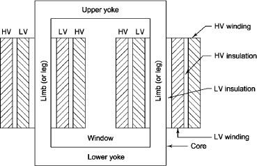
L.V. Winding placed inside and H.V. Winding placed outside with (proper insulation between the winding as it is easy to insulated L.V. Winding) than H.V. Winding.
2. Sandwiched
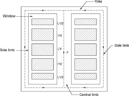
The H.V. And L.V. Winding are divided into no. Of small coils and there small windings are interleaved.
(the top and bottom winding are L.V. Coils because they are close to core)
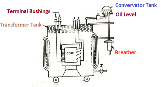
- Transformer tank : wholes assembly of winding and core placed inside the Transformer tank (sheet metal tank) which is filled with Transformer oil or insulating oil which acts as an (insulator or coolant ) MCQ
- Transformer oil : (The function of oil is to remove efficiently the heat generated in core and in winding)
- Moisture should not be allowed which creeps the insulation which achieved by closed Transformer tank.
(To increase cooling surface are tubes or fins are provided)
- Conservator tank : Above tank T/F tank there is one small tank in which same empty space is always provided above the oil level. (this space is required for oil to expand or contract due to temperature change) MCQ
However during contraction outside air can have moisture which will deteriorate the insulating properly of oil.
- Breather : The air goes in or out through the breather (To reduce the moisture content of their air . Same drying agents such as (silica gel or) calcium chloride) is used in the breather (The dust particles present in air are also removed by breather)
- Buccholz Relay : (For incipient (slowly increasing) faults
There is pipe connecting rain tank and conservator. On the pipe a protective device called Buccholz Relay is mounted.
When the Transformer is about to be faulty and draw range current the oil becomes very hot and decompose.
During this process different types of gases are liberated.(The Bucchoz Relay get operated by these gases) and gives an alarm to the operator. ɡȴ the fault continues to persist then there lay will trip off main circuit breaker to protect the Transformer.
- Explosion Vent :
An explosion Vent or relief value is the bent up pipe filled on the main tank.
(The explosion vent consist of aluminium of oil ) when the T/F becomes faulty the cooling oil get decomposed and various types of gases are liberated
(ɡȴ the gas pressure exodus certain level then the aluminium of oil (diagram) in explosion vent will burst) to release pressure. The will save main tank from getting damaged.
- Single phase transformer - for MCQs
(Symbol and principal of operation)
It is a static device which can transfer electrical energy from one ac circuit to another ac circuit without change in frequency
It can increase or decrease the voltage but with corresponding decrease or increase in current
It works on Principle 
“Mutual Induction”
A major application of transformer is to increase voltage before transmitting electrical energy over a long distance through conductors and to again reduce voltage at place where it is to be used.
Symbol
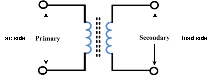
- Primary winding : (ac supply side) For MCQs
The winding which is connected to supply is called primary side
2. Secondary winding : (load side) for MCQs
The winding which is connected to load is called as secondary winding
Principle of operation
- Working : For MCQs
It works on principle of mutual Induction ie “when 2 coil are inductively coupled and if current in one coil is changed uniformly then an emf get induced in another coil”
- When alternating voltage V1 is applied to primary winding am alternating current I1 flows in it producing alternating flux in the core.
- As per Faradays Law of Electromagnetic Induction 1 an emf E1 is induced in the primary winding E = N1

- The emf induced in the primary winding is nearly equal and opporite to applied voltage V1
- Assuming leakage flux to be negligible almost whole flux produced in primary winding links with secondary winding thence emf induced in the secondary winding E2 = N2
 .
.
EMF equation
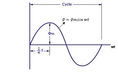
As primary winding excited by the sinusoidal alternating voltage an alternating current flows in the winding producing an alternating varying flux Ø
Ø = Øm sin wt
As per Faradays Law of Electromagnetic Induction emf E1 is induced
E1 = N1 
E1 = N1  (Ø Sin wt)
= - N1 Øm w Cos wt
Sin (90-wt)
= - Sin (wt-90)
 E1 = N1 Øm w Sin (wt-90)
 w =
w = 
 E1 =
E1 =  N1 Ø m Sin (wt-90)
Max value of E1 = E max
Is when Sin (wt-90) =  1
1
E1 max =  N1 Ø m
Hence rms value of induced EMF in primary winding
E1 rms =  =
= 
 E1 = 4.44 F Ø m N1
 Similarly RMS value of induced EMF in secondary wdg Is
E2 = 4.44 F Ø m N2
Voltage and current ratios
Voltage ratio is the ratio of primary voltage to secondary voltage in voltage transformer.
Current ratio is the ratio of primary current to secondary current in current transformer.
VP/VS = IS/IP
As voltage ratio is equal to turn ratio so
NP/NS = IS/IP
Q1>. A 2500/200 V transformer draws a no-load primary current of 0.5 A and absorbs 400 W. Find magnetising and loss currents.
Sol: Iron-loss current = No load input(W) / Primary voltage
= 400/2500 = 0.16 A
I20 = I2w + I2µ
Iµ = √I20 – I2w
= √ (0.5)2 – (0.16)2
Iµ = 0.473 A
Q2>. A 1-φ transformer has 1000 turns on primary and 200 on secondary. The no load current is 4 amp at p.f of 0.2 lagging. Find primary current and pf when secondary current is 280 A at pf of 0.6 lagging.
Sol : cos-1 0.6 = 53.130 (sin φ = 0.8)
I2 = 280/-53.130A
Φ = cos-1 0.2 = 78.50
Sin φ = 0.98
I1 = I0 + I’2
I’2 = (I2/K) ( -53.130
K = N1/N2 = 1000/200 = 5
I’2 = 280/5 (-53.130
I’2 = 56(-53.130
I1 = I0 + I’2
= 4(0.20 – j0.98) + 56(0.6 – j0.8)
= 0.80 – j3.92 + 33.6 – j44.8
I1 = 34.4 – j48.72
I1 = 59.64 ( -54.770
I lags supply voltage by 54.770
Q3) When operated at 120 V in the primary of an iron core transformer, the current in the primary is 5 amps. Find the current in the secondary if the voltage is stepped up to 400 V.
Sol: VP/VS = IS/IP
120/400 = IS/5
IS = 1.5A
Q4) A transformer with 400 turns on the primary and 60 turns on the secondary draws Solution: 0.5 amps from a 120 V line. Find Is.
Sol: NP/NS = IS/IP
400/60 = IS/0.5
IS = 3.34A
The induction motor has following important parts:-
- Stator :- it is the stationary part of induction motor and it is one of important part in induction motor.
- Rotor:- the rotor is the rotating part of induction motor which consists of rotor wdg.
- Stator winding:- this wdg. Is mounted on devastator and it generates the RMF i.e. rotating magnetic field.
- Rotor winding:- rotor winding is used to rotate the shaft of motor. This wdgis provided on rotor
- Frame :- it provides the mechanical support to the motor. It is the outer covering of motor. It protects the internal parts of motor from damage.
- Shaft:- shaft is used to connect to the load and four rotation.
- Slip rings and brushes:- slip rings are mounted on the shaft which is connected with brushes from which connection is given to the external resistant or rheostat
- Cooling fan:- this is provided for cooling purpose of motor and its internal parts.
Principle of operation of induction motor:
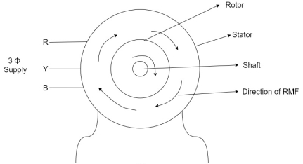
- When the 3Ф A.C supply is connected across the stator of induction motor, the current starts flowing through the stator wdg. i.ethe stator condition.
- Due to this current of flux (Ф) is established in the stator wdg. This flux (Ф) is alternating (changing) in nature. Thus this flux links with the rotor also, and a a Rotating Magnetic Field(RMF) is produced.
- This flux (Ф) induces emf in the rotor also. The RMF is produced in the air gap between stator and rotor.
- The rotor is rotating part which is till stationary, show the rotating magnetic field is cut by stationary rotor and an EMF is induced in the rotor winding. According to faraday's law of EMI the rotor EMF gives the rise to rotor current which opposes the main cause producing it according Lenz's law.
- When the stator is fed with two or three phase AC supply, a Rotating Magnetic Field (RMF) is produced. The relative speed between stator's rotating magnetic field and the rotor will cause an induced current in the rotor conductors. The rotor current gives rise to the rotor flux. According to Lenz's law, the direction of this induced current is such that it will tend to oppose the cause of its production, i.e. relative speed between stator's RMF and the rotor. Thus, the rotor will try to catch up with the RMF and reduce the relative speed.
Induction motor always runs at a speed which is less than the synchronous speed.
i.e. N < Ns
Types of induction motor:
Two main types depending upon the rotor
- Squirrel cage induction motor (squirrel cage rotor)
- Slip ring induction motor(slip ring or wound rotor)
Induction motor are also available in 1Ф supply i.e.
1. Resistance split phase induction motor
2. Capacitor start induction motor
3. Capacitor start capacitor run induction motor
4. 1Ф induction motor i.e. A.C series motors
5. Shaded pole induction motor
Torque equation of induction motor:-
Torque produced in induction motor depends upon the following factors
1.The rotor power factors ( CosФ) under running condition
2.The rotor current under running condition
3. The part of RMF which induces EMF in rotor wdgi.e. flux (Ф)
We can mathematically say that,
 , As per DC (M) equation
But in case of induction motor
Suffix 1 -> used for stator/stator parts (qty)
Suffix 2-> used for rotor/rotor parts(qty)
Therefore,  ----(1)
 = flux that induces the EMF in rotor
 = rotor current under running condition
 = P.F of rotor
But, stator vtg
 also i.e
 ----(2)
Transformation ratio i.e. given by 
Therefore,
 and hence
 also
also
 at slip ’S’ is given by
And also  at slip ‘S’ is
  =S.
=S.
Hence  in equation can be replaced by
i.e.  U
U
 =
= ----(3)----(
 )
)
4 =
= ------(4)
Subtract (3) and (4) into (1) equation we get,


 (N-m) , Torque equation of I.M.


At starting condition slip S=1
So, 
The power system has mainly three stages i.e its generation, transmission and distribution. The ways to generate power is discussed here. In over day to day life we require electricity, it has become a major system evolving in todays era with advancement in technology. As there is advancement in electronic technology, we need electricity for all those equipment’s and appliances to run. This electrical energy can be generated from various natural sources. These sources are renewable and non-renewable sources. In present system most of the energy is produced from non-renewable systems like coal, oil and natural gas. These non-renewable sources need to limit and hence energy from renewable sources are generated. The renewable sources are solar, wind, water, tidal and biomass. Below discussed plants use conventional energy sources like nuclear, hydro and thermal.
Hydro power plants:
In these stations water is used to run the turbine which is coupled to the generator. The water head needed for running the generator may be available naturally in some areas or they can also be created artificially in form of dams. These plants are eco-friendly because no fuel is required to run them.
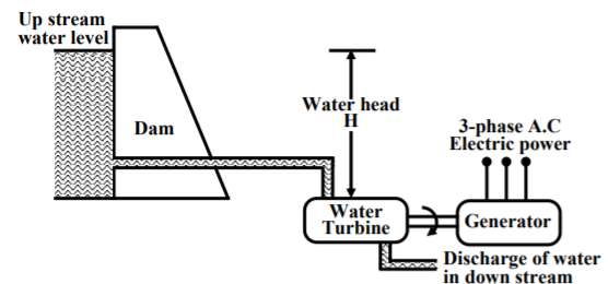
The above figure shows a hydro plant. The water from the dam is supplied to the water turbine, the potential energy is converted to kinetic energy making the turbine run. This kinetic energy from the turbine is converted to the electrical energy through generator. Water turbines generally operate at low rpm, so number of poles of the alternator are high.
Thermal Plant:
In these plants coal is burnt to produce high temperature and pressure steam in boiler. The steam produces a rotational motion when it passes through turbine. This turbine rotates and produces electricity. In India coal is present in abundance so they are commonly used. The resources used are easily available and cheap so they require less cost in installation. The main drawback of these plants is that they pollute the environment. As the coal is burnt to produce energy the leftover ash and the chimneys adds to the cost in the plant.
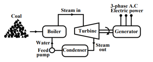
We conclude the working of thermal plant by noticing that chemical energy from coal is converted to heat and steam which the turbine converts to mechanical energy to rotate and produce electricity.
Nuclear Power Plants:
The radioactive elements like U235 and thorium are used as fuel. The nuclear reactors and heat exchanger tubes are used in place of boilers as in thermal plants.
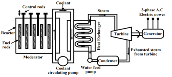
There is fission reaction takes place in the radioactive elements within the nuclear reactors. The fission reaction is a chain reaction producing huge amount of energy in the form of heat. This heat is passed to the heat exchanger tubes producing steam of very high temperature. This steam drives the turbine to produce the electricity.
Diesel power station:
The generator or alternators are moved using diesel engines to generate power. The mechanical power required for driving alternator comes from combustion of diesel engine. Due to high cost of diesel these plants are not useful for large scale. They are mainly used during power cuts in industries, hospitals and commercial buildings.
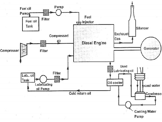
The fuel supply system in plant are storage tanks where oil is used. The strainers are used to remove solid impurities from oil before passing them to dry tank. The air intake system provides necessary air to engine for fuel combustion. Some parts in the plant have high temperatures so coolant systems are used to reduce the temperature. Compressed air is used for starting of engine.
They are simple in design and are portable. They can be stopped according to our needs. They have high thermal efficiency compared to coal. They require less space.
Solar energy:
They are also known as renewable energy sources. The energy from renewable energy sources can be used to generate power. Solar energy most easily available and free source of energy. This energy can be used in two forms solar thermal energy and solar electric energy.
I) Solar Thermal Energy: Here solar energy is converted to thermal energy with help of solar devices. They are listed below
a) Solar water heater: These water heaters use solar energy to heat water and then can be used for various purposes. They are used in hotels, dairies, industries etc. There is a solar collector mounted on roof top to take the sunlight. The tubes are attached to these collectors and liquid whuch needs to be heated is passed through it. The heat builds up in the collector, which is passed to the fluid passing through the tubes. There is an insulated tank to store this hot water.
b) Solar cooker: They are used to cook food using sunlight. There are of two types box type and parabolic type. The box type cooker is painted black to absorb more heat and cook the food. The parabolic type solar cooker has a collector parabolic form which accommodates cooking vessel in at its focal point. This cooker is designed to direct the solar heat to a secondary reflector inside the kitchen, which focuses the heat to the bottom of a cooking pot. It is also possible to actually fry, bake and roast food.
II) Solar Electric Energy: Here PV cells are used which are made of silicon.
a) Solar Photovoltaic: As soon as PV cells are exposed to light the electrons are released and current is produced. The cell is covered with metal grid to direct the flow of current. These cells connected in a panel are also used. These PV panels are installed above the roof. These panels are connected in series or parallel. The generation of power depends upon the amount of heat received from sun.
b) Solar water pumps: The motor required to run the pump uses electricity generated by solar panels. It consists of a photovoltaic array mounted on a stand and a motor-pump set compatible with the photovoltaic array. It converts the solar energy into electricity, which is used for running the motor pump set. The pumping system draws water from the open well, bore well, stream, pond, canal etc
Wind Energy:
Most commonly wind turbines are used. There are two types of turbines vertical axis wind turbine which has rotational vertical axis. The other is horizontal rotational axis. Wind electric generator converts kinetic energy available in wind to electrical energy by using rotor, gear box and generator. The generation of power depends upon the speed of wind. Wind turbines for remote homes (off the grid) generate DC current for battery charging. Wind turbines for remote water pumping generate 3 phase AC current suitable for driving an electrical submersible pump directly. Wind turbines suitable for residential or village scale wind power range from 500 Watts to 50 kilowatts.
Ocean Energy:
The ocean waves, tides or thermal energy provide energy to ocean. The ocean contains two types of energy thermal energy from sun and mechanical energy from tides. The oceans energy is used to produce electricity by closed loop system, open loop system or hybrid type. The oceans warm surface water is used to produce vapours from the working fluid (ammonia). The vapours produced expands and runs the turbine. The turbine than activates generator to produce electricity. Open-cycle systems actually boil the seawater by operating at low pressures. This produces steam that passes through a turbine / generator. The hybrid systems combine both closed-cycle and open-cycle systems. India has the World's largest programmes for renewable energy. Several renewable energy technologies have been developed and deployed in villages and cities of India. A Ministry of Non-Conventional Energy Sources (MNES) created in 1992 for all matters relating to Non-Conventional / Renewable Energy. Government of India also created Renewable Energy Development Agency Limited (IREDA) to assist and provide financial assistance in the form of subsidy and low interest loan for renewable energy projects.
The power distribution system employs different techniques depending upon the requirements. The electricity is provided to the consumers from the electric power supply systems. The power transmission cab be classified as:
According to nature of current:
- DC Distribution System
- AC Distribution system
According to type of construction:
- Overhead distribution system
- Underground distribution system
DC Transmission: The system requires only two conductors. They have reduced insulation cost. This system has 70% less potential stress than AC transmission systems. The network required for transmission is simple compared to AC transmission.
AC Transmission: This is most commonly used transmission for electrical energy. The main advantage of such systems is the voltages can be stepped up/down easily. The maintenance cost is also less.
Primary distribution: The primary distribution is carried by 3-phase, 3-wire system. This distribution is used which operates higher voltages. This distribution system is used mainly in factories and industries. They also feed small substation from which secondary distribution is carried out. The voltages for which primary distribution is used are 11kV, 6.6kV and 3.3kV.
Secondary distribution: This distribution is used to feed residential customers. The residential supply is of 230v. This transmission is carried out by 3-phase, 4-wire system.
References:
1. Robert L. Boylestad. Introductory circuit analysis. (Twelfth edition). Pearson
Education, New Delhi. (2012)
2. Cotton, H. Electrical technology. (Seventh edition). CBS Publishers and Distributors,
New Delhi. (2005)
3. Leonard S. Bobrow. Fundamentals of electrical engineering. Oxford University Press,
New Delhi.(1996).
4. Rajendra Prasad. Fundamentals of electrical engineering. (Second edition). PHI
Learning, New Delhi.(2009)
5. Edward Hughes. Electrical technology. Addison Wesley Longman, Boston. (1995).