Module II
Review of electromagnetic induction
Faraday’s Laws of Electromagnetic Induction consists of two laws. The first law describes the induction of emf in a conductor and the second law quantifies the emf produced in the conductor
i) Faradays First law of EMI: Whenever a conductor is placed in a varying magnetic field, an electromotive force is induced. If the conductor circuit is closed, a current is induced which is called induced current.
Ii) Faradays Second law of EMI: The induced emf in a coil is equal to the rate of change of flux linkage.

 = electromotive force
N = Number of turns
 = magnetic flux
- Increase in the number of turns in the coil increases the induced emf
- Increasing the magnetic field strength increases the induced emf
- Increasing the speed of the relative motion between the coil and the magnet, results in the increased emf
Lenz Law:
The induced electromotive force with different polarities induces a current whose magnetic field opposes the change in magnetic flux through the loop in order to ensure that original flux is maintained through the loop when current flows in it.
E = - 
E: electromotive force
 : magnetic flux
What is Self-Induction?
When there is a change in the current or magnetic flux of the coil, an opposed induced electromotive force is produced. This phenomenon is termed as Self Induction. When the current starts flowing through the coil at any instant, it is found that that the magnetic flux becomes directly proportional to the current passing through the circuit. The relation is given as:
ϕ= I
ϕ = L I
Where L is termed as self-inductance of the coil or the coefficient of self-inductance. The self-inductance depends on the cross-sectional area, the permeability of the material or the number of turns in the coil.
The rate of change of magnetic flux in the coil is given as,

What is Mutual Induction?
We take two coils, and they are placed close to each other. The two coils are P- coil (Primary coil) and S- coil (Secondary coil). To the P-coil, a battery, and a key is connected wherein the S-coil a galvanometer is connected across it. When there is a change in the current or magnetic flux linked with two coils an opposing electromotive force is produced across each coil, and this phenomenon is termed as Mutual Induction. The relation is given as:
ϕ = I
ϕ = M I
Where M is termed as the mutual inductance of the two coils or the coefficient of the mutual inductance of the two coils.
The rate of change of magnetic flux in the coil is given as,

- MUTUAL INDUCTANCE:-
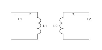
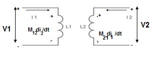
 mutual inductance on 1 due to 2
 mutual inductance on 2 due to 1
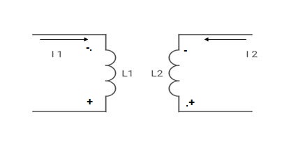
● If current is entering at dot  then it will produce mutual induction or it will produce a voltage with positive polarity on
  .
.
● If current is leaving at dot  then it will produce a voltage with negative polarity on
  .
.
Voltage on 2 due to 1 = 
Voltage on 1 due to 2 = 
- When current is entering or leaving from both dots.
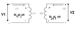
 -
-  -
-  = 0 ⎼⎼⎼⎼⎼⎼ 1
 -
-  -
-  = 0 ⎼⎼⎼⎼⎼⎼2
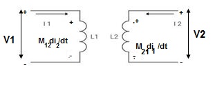
 -
-  -
-  = 0 ⎼⎼⎼⎼⎼⎼⎼1
 -
- 
 = 0 ⎼⎼⎼⎼⎼⎼⎼2
2. When current is entering from one dot and leaving the other
 -
-  +
+  = 0 ⎼⎼⎼⎼⎼⎼⎼⎼1
 -
-  +
+  = 0 ⎼⎼⎼⎼⎼⎼⎼⎼2
- When current is entering in both dots
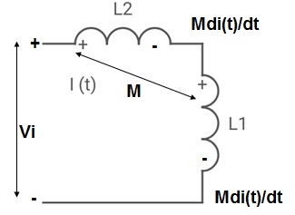
Find 
If 


II. When current leaves both dots
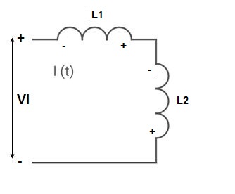 Find
Find 


III. When current enters from  and leaves
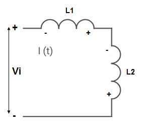 Find
Find 


IV. When current leaves  and enters
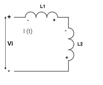

Example 1. Find 
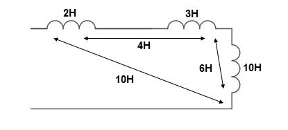


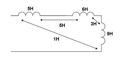
Example 2. Find 


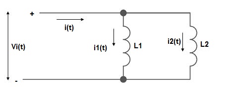
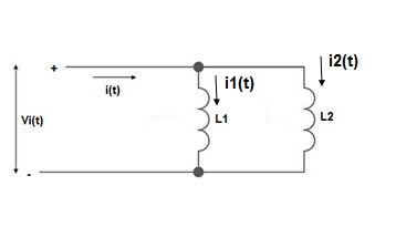
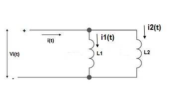
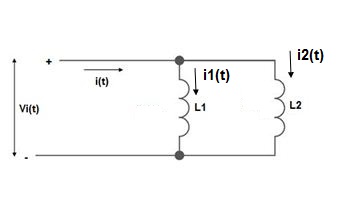
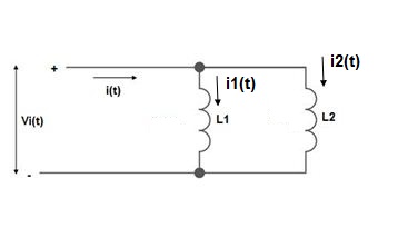
PARALLEL COMBINATION: -




The MMF is defined as the work done in moving the unit magnetic pole (1weber) once around the magnetic circuit.
The magnetomotive force (MMF) is required to drive the magnetic flux in the magnetic circuit. The magnetic pressure, which sets up the magnetic flux in the circuit as called Magnetomotive Force. The SI unit of MMF is Ampere-turn (AT), and their CGS unit is G (gilbert). The MMF for the inductive coil shown in the figure below is expressed as
F=NI
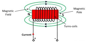
The strength of the MMF is equivalent to the product of the current around the turns and the number of turns of the coil.
Magnetic Flux:
The number of magnetic lines of forces set up in a magnetic circuit is called Magnetic Flux. It is analogous to electric current, I in an electric circuit. Its SI unit is Weber (Wb) and its CGS unit is Maxwell. It is denoted by φB.
ΦB=B.S
ΦB=B.S Cos
B – the magnitude of the magnetic field
S – area of surface
θ – angle between the magnetic field lines and perpendicular distance normal to the surface area
Magnetic flux for a closed surface
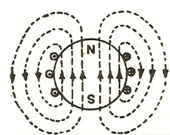
ΦB= =0
=0
Magnetic flux for open surface is
E=
E=
E – electromotive force
v – velocity of the boundary
E – electric field
B – magnetic field
øB - magnetic flux through the open surface
The magnetic flux through a closed surface is always zero, but in the open surface, it is not zero.
Flux density
It is defined as the flux passing per unit area through a plane at right angles to the flux. It is denoted by B. Its unit is Weber/m2.
B=  Wb/m2
Wb/m2
Flux intensity/Magnetic Field Strength
It is also known as magnetic field strength. It is numerically equal to the force experienced by the N-pole of one weber placed at that point. It is denoted by H.
H=  A/m or N/Wb
Galvanometer coil
A moving coil galvanometer is an instrument which is used to measure electric current. A current-carrying coil when placed in an external magnetic field experiences magnetic torque. The angle through which the coil is deflected due to the effect of the magnetic torque is proportional to the magnitude of current in the coil. The moving coil galvanometer is made up of a rectangular coil that has many turns and it is usually made of thinly insulated or fine copper wire that is wounded on a metallic frame.
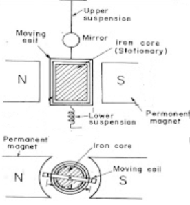
The coil is free to rotate about a fixed axis. A phosphor-bronze strip that is connected to a movable torsion head is used to suspend the coil in a uniform radial magnetic field. A cylindrical soft iron core is symmetrically positioned inside the coil to improve the strength of the magnetic field and to make the field radial. The lower part of the coil is attached to a phosphor-bronze spring having a small number of turns. The other end of the spring is connected to binding screws.
We know that torque τ = force x perpendicular distance between the forces
τ = F × b
Substituting the value of F we already know,
Torque τ acting on single-loop of the coil = BIl × b
Where lx b is the area A of the coil,
Hence the torque acting on n turns of the coil is given by
τ = nIAB
The magnetic torque thus produced causes the coil to rotate, and the phosphor bronze strip twists. In turn, the spring S attached to the coil produces a counter torque or restoring torque kθ which results in a steady angular deflection.
Under equilibrium condition:
kθ = nIAB
Here k is called the torsional constant of the spring (restoring couple per unit twist). The deflection or twist θ is measured as the value indicated on a scale by a pointer which is connected to the suspension wire.
θ= ( nAB / k)I
Therefore θ ∝ I
The quantity nAB / k is a constant for a given galvanometer. Hence it is understood that the deflection that occurs the galvanometer is directly proportional to the current that flows through it.
The torque for moving iron instrument is T= 
This can be used for both AC and DC.
The moving element is a plate or soft iron. The plate is placed such that is moves freely in the magnetic field of stationary coil. These stationary coils are electromagnets. These magnets are temporary magnets whose field strength varies according to the amount of current passing through it.
They are classified as
i) Repulsive moving iron instrument: It has two vanes one is fixed and the other is moving. When current passes through stationary coil the vane gets magnetized and a repulsive force is generated between them. Due to this repulsion the moving coil moves away from the fixed vane. The spring coil provides controlling torque. The damping torque induced opposes the movement of the coil. These instruments are not affected by the direction of current flow.
Ii) Attractive moving iron instrument: In this the iron plate is attracted from the weaker field towards the stronger one. The stationary coil is flat and has narrow opening. The flat disc of iron core is moving element. The current through stationary coil produces the magnetic field and attracts the iron coil.
Moving coil type ammeter:
The basic principle of operation is same as discussed for voltmeter in above section. The deflection torque is given as
Td= BiNlb Nm
B: flux density
i: current through coil
l: length of coil
b: breadth of coil
N: number of turns in coil
The range of instrument can be increased by adding a resistance in parallel as shown below.
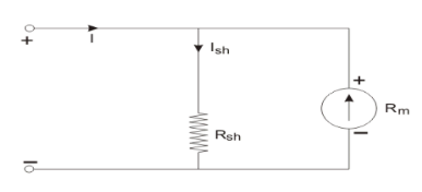
Rsh=
Rm: Ammeter resistance
Ish: current through shunt resistance
I: total current
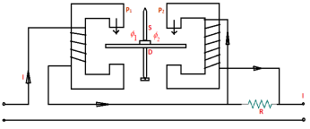
Induction type Ammeter
The working principle is same as discussed in above section. They are of two types:
i) Split phase type: It has two magnets M1 and M2 in series. The shunt resistance R is connected to M2. The current in M2 lags line current. The deflection torque is Td = φ1m φ2m sinα
Ii) Shaded Pole Type: In this case the exciting coil is placed on poles. The current proportion to current or voltage is measured.
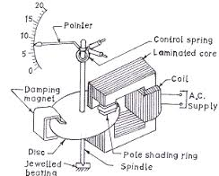
In the air gap of electromagnet aluminium disc mounted on a spindle is inserted. The spring is attached to the pointer and both are mounted on spindle. The spring provides the controlling torque.
The deflection torque is Td = φ1φ2 sinα
Construction
The moving element is a plate or soft iron. The plate is placed such that is moves freely in the magnetic field of stationary coil. These stationary coils are electromagnets. These magnets are temporary magnets whose field strength varies according to the amount of current passing through it. They can be used for both AC as well as DC.
Operation
These instruments use moving iron to measure the flow of current or voltages. When the iron is placed near magnetic field it is attracted towards the field. The force of attraction depends upon the strength of field.
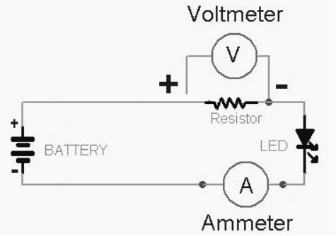
The stationary coil of copper or aluminium wire acts as electromagnet when current passes through it. The plate when passes through this coil increases the inductance of stationary coil. The electromagnets attract the plate. The plate passes through coil from the least reluctance path. This plate experiences a repulsion due to electromagnets. The repulsion force increases the strength of the coil inductance. This happens because the inductance and reluctances are inversely proportional to each other.
One iron vane is held fixed to the coil frame and other is free to rotate, carrying with it the pointer shaft. Two irons lie in the magnetic field produced by the coil that consists of only few turns if the instrument is an ammeter or of many turns if the instrument is a voltmeter. Current in the coil induces both vanes to become magnetized and repulsion between the similarly magnetized vanes produces a proportional rotation
The moving iron instrument can be classified as
i) Repulsive moving iron instrument: It has two vanes one is fixed and the other is moving. When current passes through stationary coil the vane gets magnetized and a repulsive force is generated between them. Due to this repulsion the moving coil moves away from the fixed vane.
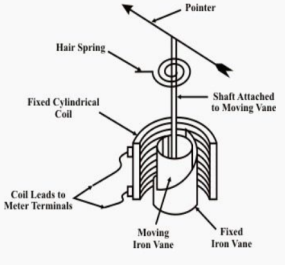
The spring coil provides controlling torque. The damping torque induced opposes the movement of the coil. These instruments are not affected by the direction of current flow.
Ii) Attractive moving iron instrument: In this the iron plate is attracted from the weaker field towards the stronger one. The stationary coil is flat and has narrow opening. The flat disc of iron core is moving element. The current through stationary coil produces the magnetic field and attracts the iron coil.
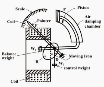
The iron plate then gets attracted from low magnetic field to high magnetic field. The strength through which the iron plate is deflected is directly proportional to the current flowing through it.
Advantages:
They are low cost instruments. They are easy to assemble. They have less friction error. They are used in both AC and DC.
Moving coil type voltmeter:
Construction:
This consists of a magnet system made of materials like alcomax and alnico giving high field strength. There is a moving coil freely moving between the permanent magnets. This coil is wound with copper wire and placed in aluminium rectangular case. The torque is due to movement of aluminium in magnetic field. The spring is connected to measure the deflection produced. The meter connected to the spring shows the reading.
Working Principle:
It is called as Permanent magnet moving coil (PMMC). They measure only DC. This instrument measures the current through coil by angular deflection in magnetic field. A coil is placed between two permanent magnets in these types of instrument to produce magnetic field. The current carrying conductor when placed in the field experiences a force which is proportional to the amount of current through it. When the torques are balanced the moving coil stops. The angular deflection can be measured.
The deflection torque equation is given as
Td=NBldI
N: Number of turns
B: Magnetic flux density
l: length of moving coil
d: width of moving coil
I: Electric current
The below circuit extends the range of voltmeter by connecting resistance in series with the meter.
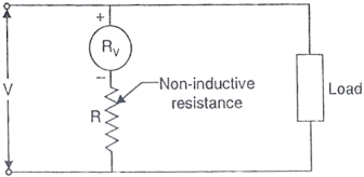
The external resistance connected will be
R= [V-V1/V1] x RV
RV: Voltmeter resistance
R: external resistance
V1: voltage across voltmeter
Induction type meter:
In all induction meters we have two fluxes which are produced by two different alternating currents on a metallic disc. Due to alternating fluxes there is an induced emf, the emf produced at one point (as shown in the figure given below) interacts with the alternating current of the other side resulting in the production of torque.
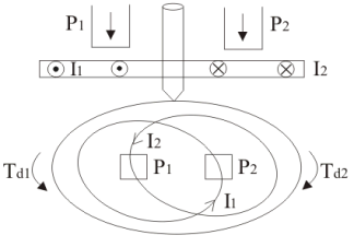
Let F1 =flux at point 1
F2= flux at point 2
Then
F1 = Fm1 sinwt
F2= Fm2 sin (wt-B)
B=phase difference between two fluxes.
The induced emf for both points will be
E1= - 
E2= - 
The value of eddy current at point 1 is
I1 = E1/Z = K x f x F1
The phasor is shown below
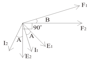
The deflection torque at point 1 will be
Td1= K x F2 x I1x cos(90-B+A) = K x F1 x (f/Z) cos(90-B+A) x F2
The deflection torque at point 2 will be
Td2= K x F1 x (f/Z) x cos(90+B+A) x F2
Total torque is
Td1- Td2 = K x F1 x F2 x (f/Z) sinB cos A
This instrument is used to measure the electric power of electric circuits. It has current and voltage coils. The wattmeter measures the power of the electric circuit.
P= VI cosφ
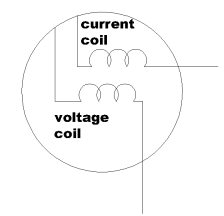
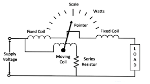
There are two types of wattmeter
i) Electro-dynamometer type wattmeter
They are moving coil of instruments. The fixed coil produces the operating field. When AC flows through fixed coil magnetic field is produced. The moving coil starts moving and the pointer fluctuates. They are highly accurate.
Ii) Induction Type wattmeter
They are used for both AC and DC. It consists of two electromagnets and one is excited by the current with exciting winding. This winding is connected in series. The exciting coil is in parallel to the circuit. The winding of first magnet carries line current and other coil carries voltage. The coil connected to supply and flux lags 90o to voltage. The torque is proportional to the power in the load circuit. Due to this torque the spring fluctuates and pointer notes the reading.
Uses: They are used in laboratories, industries, transmission line and power distribution.
These meters measure power consumption. They are used in our houses also. There are basically two types:
i) Electric Motor energy meters: They are further classified as
a) Ampere hour mercury meter: It consists of copper disc mounted on spindle. The disc revolves around the magnets present. The gap between the magnets is filled with mercury.
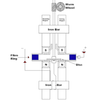
Here the current to be measured flows through the mercury radially into the centre of disc. It flows out through the spindle and bearings. The magnetic field due to M2 exerts a force on the right-hand side of disc producing the driving torque.
b) Commutator motor energy meter: They consists of wound winding armature and a commutator. 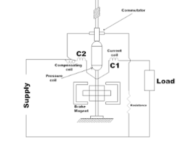
It has two fixed coils C1 and C2. The coil is wounded with copper wire and is connected in series with supply. The electromagnetic field is produced in both the coils and this field is proportional to the current to be measured. This field rotates the armature. The current is proportional to supply voltage. Due to the reaction between electromagnetic field and armature torque is produced. The braking torque is produced due to the eddy currents. This eddy current is produced in gap in which the disc which is in between the two magnets.
c) Induction type single phase energy meter: These are AC meters. These are the domestic energy meters which are widely used. They measure power in k-watthours.
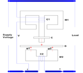
It has two magnets M1 and M2. The first magnet is known as series magnet and the second magnet is known as shunt magnet. The first magnet is excited by line current. The electromagnet produces alternating flux φ1. This flux φ1 is proportional φ1 to the phase with line current. The second magnet produces the lagging flux φ2 which is proportion to supply voltage.
The two fluxes and the eddy current react and produces driving torque on the disc. The two magnets produce barking torque.
Ii) Electrolytic Energy meters: It is ampere-hour energy meter used in only DC circuits. They work on the principle of faraday law of electrolysis. They can be employed for AC circuits with using rectifiers.
Uses: They are used in domestic areas for calculation of power consumption. They are also used in industrial areas for controlling electric power.
References:
1. Robert L. Boylestad. Introductory circuit analysis. (Twelfth edition). Pearson
Education, New Delhi. (2012)
2. Cotton, H. Electrical technology. (Seventh edition). CBS Publishers and Distributors,
New Delhi. (2005)
3. Leonard S. Bobrow. Fundamentals of electrical engineering. Oxford University Press,
New Delhi.(1996).
4. Rajendra Prasad. Fundamentals of electrical engineering. (Second edition). PHI
Learning, New Delhi.(2009)
5. Edward Hughes. Electrical technology. Addison Wesley Longman, Boston. (1995).