UNIT 1
INTRODUCTION TO ENGINEERING DRAWING
To record information on paper (or another surface), instruments and equipment are required. Even for drawings made freehand, pencils, erasers, and sometimes coordinate paper or other special items are used. The lines made on drawings are straight or curved (including circles and arcs). They are made with drawing instruments, which are the necessary tools for laying down lines on a drawing in an accurate and efficient manner. To position the lines, a measuring device, a scale, is needed.
The various instruments will be described in detail later, but the opening of this chapter will serve as an introduction. To draw straight lines, the T square, with its straight blade and perpendicular head, or a triangle is used to support the stroke of the pencil. To draw circles, a compass is needed. In addition to the compass, the draftsman needs dividers for spacing distances and a small bow compass for drawing small circles. To draw curved lines other than circles, a French curve is required. A scale is used for making measurements.
Just as in English textbook the correct words are used for making correct sentences; in Engineering Graphics, the details of various objects are drawn by different types of lines. Each line has a definite meaning and sense to convey.
IS 10714 (Pint 20): 2001 (General principles of presentation on technical drawings) and SP 46:2003specify the following types oflines and their applications:
1. Visible Outlines, Visible Edges: (Continuous wide lines) the lines drawn to represent the visible outlines/ visible edges / surface boundary lines of objects should be outstanding in appearance.
2. Dimension Lines: (Continuous narrow Lines) Dimension Lines are drawn to mark dimension.
3. Extension Lines: (Continuous narrow Lines) There are extended slightly beyond the respective dimension lines.
4. Construction Lines: (Continuous narrow Lines) Construction Lines are drawn for constructing drawings and should not be erased after completion of the drawing.
5. Hatching / Section Lines: (Continuous Narrow Lines)
Hatching Lines are drawn for the sectioned portion of an object. These are drawn inclined at an angle of 45° to the axis or to the main outline of the section.
6. Guide Lines: (Continuous Narrow Lines)
Guide Lines are drawn for lettering and should not be erased after lettering.
7. Break Lines: (Continuous Narrow Freehand Lines)
Wavy continuous narrow line drawn freehand is used to represent break of an object.
8. Break Lines: (Continuous Narrow Lines with Zigzags)
Straight continuous arrow line with zigzags is used to represent break of an object.
9. Dashed Narrow Lines: (Dashed Narrow Lines)
Hidden edges / Hidden outlines of objects are shown by dashed lines of short dashes of equal lengths of about 3 mm, spaced at equal distances of about 1 mm. The points of intersection of these lines with the outlines / another hidden line should be clearly shown.
10. Center Lines: (Long-Dashed Dotted Narrow Lines)
Center Lines are drawn at the center of the drawings symmetrical about an axis or both the axes. These are extended by a short distance beyond the outline of the drawing.
11. Cutting Plane Lines:
Cutting Plane Line is drawn to show the location of a cutting plane. It is long-dashed dotted narrow line, made wide at the ends, bends and change of direction. The direction of viewing is shown by means of arrows resting on the cutting plane line.
12. Border Lines
Border Lines are continuous wide lines of minimum thickness 0.7 mm.
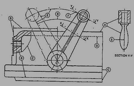
Figure 1 Types of lines
Table 2 Types of lines and their applications
Line | Description | General application |
| Continuous thick or continuous wide | Visible outlines, visible edges, main representation in diagrams, maps; system lines |
| Continuous thin (narrow) (straight or curved) | Imaginary lines of intersection; grid, dimension. Extension, projection, reference lines and hatching. |
| Continuous thin (narrow) freehand. | Limits of partial or interrupted views and sections, if the limit is not a chain thin line. |
| Continuous thin (narrow) with zigzags (straight) | Long break line |
 | Dashed thick (wide) | Line showing permissible of surface treatment. |
 | Dashed thin (narrow) | Hidden outline; hidden edges |
 | Chain thin Long-dashed dotted (narrow) | Centre line; lines of symmetry; trajectories; pitch circle of gears, pitch circle of holes. |
 | Chain thick or long - dashed (dotted) wide | Indication of lines or surfaces to which a special requirement applies. |
Line widths:
Line width means line thickness
Choose line widths according to the size of the drawing from the following range: 0.13, 0.18, 0.25, 0.35, 0.5, 0.7 and 1 mm.
Precedence of Lines
1. When a Visible Line coincides with a Hidden Line or Center Line, draw the Visible Line. Also, extend the Center Line beyond the outlines of the view.
2. When a Hidden Line coincides with a Center Line, draw the Hidden Line.
3. When a Visible Line coincides with a Cutting Plane, draw the Visible Line.
4. When a Center line coincides with a Cutting Plane, draw the Center Line and show the
Cutting Plane line outside the outlines of the view at the ends of the Center Line by thick dashes.
Graphic representation of the shape of a part, machine, or structure gives one aspect of the information needed for its construction. To this must be added, to complete the description, figured dimensions, notes on material and finish, and a descriptive title—all lettered, freehand, in a style that is perfectly legible, uniform, and capable of rapid execution. As far as the appearance of a drawing is concerned, the lettering is the most important part. But the usefulness of a drawing, too, can be ruined by lettering done ignorantly or carelessly, because illegible figures are apt to cause mistakes in the work.
Single stroke lettering:
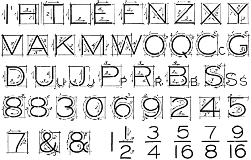
By far the greatest amount of lettering on drawings is done in a rapid single-stroke letter, either vertical or inclined, and every engineer must have absolute command of these styles.
The term "single-stroke," or "one-stroke," does not mean that the entire letter is made without lifting the pencil or pen but that the width of the stroke of the pencil or pen is the width of the stem of the letter.
Guide lines:
Always draw light guide lines for both tops and bottoms of letters, using a sharp pencil. Figure 1 shows a method of laying off several equally spaced lines. Draw the first base line; then set the bow spacers to the distance wanted between base lines and step off the required number of base lines. Above the last line mark the desired height of the letters.
Lettering in Pencil:
Good technique is as essential in lettering as in drawing. The quality of the lettering is important whether it appears on finished work to be reproduced by one of the printing processes or as part of a pencil drawing to be inked. In the first case, the penciling must be clean, firm, and opaque; in the second, it may be lighter.
Drawing of a component, in addition to providing complete shape description, must also furnish information regarding the size description. These are provided through the distances between the surfaces, location of holes, nature of surface finish, type of material, etc. The expression of these features on a drawing, using lines, symbols, figures and notes is called dimensioning.
Principles of Dimensioning
Some of the basic principles of dimensioning are given below.
1. All dimensional information necessary to describe a component clearly and completely shall be written directly on a drawing.
2. Each feature shall be dimensioned once only on a drawing, i.e., dimension marked in one view need not be repeated in another view.
3. Dimension should be placed on the view where the shape is best seen (Fig.2)
4. As far as possible, dimensions should be expressed in one unit only preferably in millimeters, without showing the unit symbol (mm).
5. As far as possible dimensions should be placed outside the view (Fig. 3).
6. Dimensions should be taken from visible outlines rather than from hidden lines (Fig. 4).
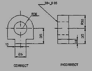
Figure 2
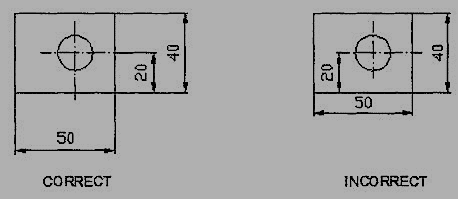
Figure 3
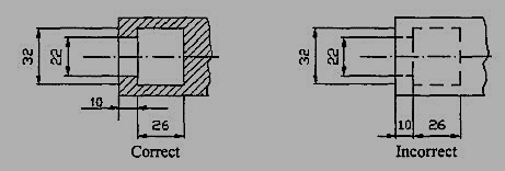
Figure 4
7. No gap should be left between the feature and the start of the extension line (Fig.5).
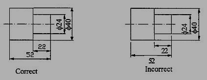
Figure 5 Marking of Extension lines
8. Crossing of center lines should be done by a long dash and not a short dash (Fig.6).
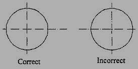
Figure 6 Crossing of Centre lines
Execution of dimensions:
1. Projection and dimension lines should be drawn as thin continuous lines. Projection lines should extend slightly beyond the respective dimension line. Projection lines should be drawn perpendicular to the feature being dimensioned. If the space for dimensioning is insufficient, the arrow heads may be reversed, and the adjacent arrow heads may be replaced by a dot (Fig.7). However, they may be drawn obliquely, but parallel to each other in special cases, such as on tapered feature (Fig.8).
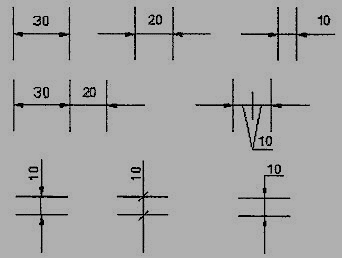
Figure 7 Dimensioning in narrow spaces

Figure 8 dimensioning a tapered feature
2. A leader line is a line referring to a feature (object, outline, and dimension). Leader lines should be inclined to the horizontal at an angle greater than 30°. Leader line should terminate,
(a) With a dot, if they end within the outline of an object (Fig 9(a).
(b) With an arrow head, if they end on outside of the object (Fig 9(b)).
(c) Without a dot or arrow head, if they end on dimension line (Fig.9(c)).

Figure 9 Termination of leader lines
Dimension Termination and Origin Indication
Dimension lines should show distinct termination in the form of arrow heads or oblique strokes or where applicable an origin indication (Fig.10). The arrow head included angle is 15°. The origin indication is drawn as a small open circle of approximately 3 mm in diameter. The proportion length to depth 3: 1 of arrow head is shown in Fig.11.
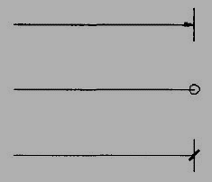
Figure 10 Termination of dimension lines
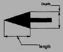
Figure 11 Proportions of an arrow head
Methods of Indicating Dimensions
The dimensions are indicated on the drawings according to one of the following two methods.
- Method I (Aligned method)
Dimensions should be placed parallel to and above their dimension lines and preferably at the middle, and clear of the line. (Fig. 12).
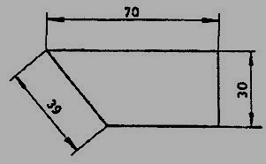
Figure 12
Dimensions may be written so that they can be read from the bottom or from the right side of the drawing. Dimensions on oblique dimension lines should be oriented as shown in Fig.13a and except where unavoidable, they shall not be placed in the 30° zone. Angular dimensions are oriented as shown in Fig.13b.
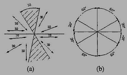
Figure 13 Angular dimensioning
2. Method 2 ( Uni-directional method)
Dimensions should be indicated so that they can be read from the bottom of the drawing only. Non-horizontal dimension lines are interrupted, preferably in the middle for insertion of the dimension (Fig.14a).
Angular dimensions may be oriented as in (Fig.14b)

Figure 14Uni-directional method
Simple Geometrical constructions
Engineering drawing consists of many geometrical constructions. A few methods are illustrated here without mathematical proofs.
1. To divide a straight line into a given number of equal parts say 5.
Construction (Fig. 15)
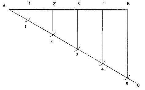
Figure 15 dividing a line
- Draw AC at any angle θ to AB.
- Construct the required number of equal parts of convenient length on AC like 1, 2, and 3.
- Join the last point 5 to B
Iv. Through 4, 3, 2, 1 draw lines parallel to 5B to intersect AB at 4', 3’, 2’ and 1'.
2. To divide a line in the ratio 1: 3: 4.
Construction (Fig. 16)
As the line is to be divided in the ratio 1:3:4 it must be divided into 8 equal divisions. By following the previous example divide AC into 8 equal parts and obtain P and Q to divide the line AB in the ratio 1:3:4.
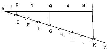
Figure 16
3. To bisect a given angle.
Construction (Fig. 17)
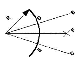
Figure 17
- Draw a line AB and AC making the given angle.
- With center a and any convenient radius R draws an arc intersecting the sides at D and E.
- With centers D and E and radius larger than half the chord length DE, draw arcs intersecting at F.
- Join AF, <BAF = <PAC.
Scales
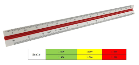
Scales, are made in various number of graduations to meet the requirements of many kinds of work. For convenience, scales are classified according to their most-common uses.
Mechanical Engineers Scale:
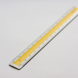
These are divided and numbered in such a way that fractions of inches represent inches. The most common ranges are 1/8, 1/4, 1/2, and 1 in. To the inch. These scales are known as the size scales because the reduced size also represents the ratio of size, as for example one-eighth size.
Mechanical engineer's scales are almost always "full divided"; that is, the smallest divisions run throughout the entire length.
They are generally graduated with the marked divisions numbered from right to left, as well as from left to right, as shown in Figure Mechanical engineer's scales are used mostly for drawings of machine parts and small structures where the drawing size is more than one-eighth the size of the actual object.
Civil Engineers Scale:
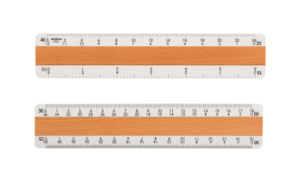
These are divided into decimals with divisions ranging from 10, 20, 30, 40, 50, 60, and 80 to the inch. Such a scale is usually full divided and is sometimes numbered both from left to right and right to leave. Civil engineer's scales are most used for plotting and drawing maps, although they are convenient for any work where divisions of the inch in tenths is required.
Metric Scales:
Metric scales are supplied in all the styles and sizes and materials of other scales. They are usually full-divided and are numbered in meters, centimeters, or millimeters depending upon the reduction in size. Typical size reductions are: 1:1, 1:2, 1:5, 1:10, 1:20, 1:25, 1:33.3, 1:50, 1:75, 1:80, 1: 100, 1: 150. Also available are metric equivalent scales for direct conversion of English scales.
