Unit - 3
Non- Traditional Machining Processes
3.1.1 Ultrasonic Machining Process, Working Principles & Advantages:
With its superior performance, ultrasonic machining is revolutionising the manufacturing industry. The main reason this machining technology is used in the industrial industry is that it produces less heat. All ultrasonic machining operations are both cost-effective and yield the greatest results. Ultrasonic machining is an abrasive method that uses a vibrating tool and the indirect passage of abrasive particles towards the work piece to turn any material into a hard and brittle state. It is a machining method with a modest rate of material removal.
Ultrasonic Machining
Ultrasonic impact grinding, also known as ultrasonic vibration grinding, is a process that utilises a vibrating tool that oscillates ultrasonic frequencies to remove material from a work piece. An abrasive slurry travels between the tool and the work piece during the process. As a result, the tool and the work piece never come into contact. The weight of the procedure is rarely more than two pounds.
Ultrasonic Machine is Useful for Hard Material
This approach is ideal for working with hard materials such ceramic matrix composites, ruby, piezo-ceramics, glass, ceramics, Quartz, ferrite, diamonds, technical ceramics, alumina, PCD, sapphire, CVD silicon carbide, and others.
Ultrasonic Machining Process
In comparison to the work piece, the tool used in the machine to cut the materials is made of a soft material. Soft steels and nickel are commonly used in the tool's construction. When the tool vibrates, abrasive slurry (liquid) with abrasive grains and particles is introduced. The abrasive slurry is introduced in small amounts until the workpieces engage with the grains. The work piece's brittleness abrades the surface due to the liquid particles introduced, while the tool gradually deforms.

Working Principle of Ultrasonic Machining
The amount of time spent on an ultrasonic machine is entirely dependent on the vibrating tool's frequency. It also depends on the particle size of the abrasive slurry, as well as its stiffness and viscosity. Because they are more stiff than others, the grains utilised in the abrasive fluid are commonly boron carbide or silicon carbide. If the slurry fluid has a low viscosity, the abrasive can be easily swept away.
Ultrasonic Machining Advantages and Disadvantages
Learn about the benefits and drawbacks of the machining process so you can make the best decision:
Advantages
1. Machining of various hard materials
2. Produces well-structured and polished results
3. It generates less heat.
4. Different hole cut forms due to the tool's vibratory motion
Disadvantages
1. Requires a higher level of honesty and ability.
2. There is no certified radiography record.
3. Defects are caused by excessively large grain sizes.
4. Due to erroneous signs and a misunderstanding of the process, more repairs may be required.
Ultrasonic machines are the future of machining, and they're already being used all over the world to make hard and brittle materials for industrial applications. The ultrasonic machine can conduct a wide range of tasks, which can aid industrialists in a variety of ways. Advanced technology creates solutions that help to expand market potential while also making things easier.
The applications of Ultrasonic Machining are:
1. Machining intricately formed products with extreme precision.
2. Drilling any kind of round hole
3. Brittle materials should be ground.
4. Creating a profile for the holes.
5. Engraving
6. Trepanning and coining are the sixth and seventh steps in the trepanning and coining
7. Threading
8. Hard material slicing and broaching
9. Glass and ceramics machining
10. Tungsten machining for accurate mineral stones.
11. Die piercing and separating off operations.
12. This is accurate enough to be employed in the manufacture of micro-electromechanical system components like micro-structured glass wafers.
13. Diamonds are cut into the shapes that are wanted.
Key takeaways:
• In ultrasonic machining, two types of transducers have been used: piezoelectric and magneto strictive: piezoelectric transducer This is made up of two metal electrodes coated on the surface of a piezoelectric ceramic, such as barium titanate.
• Ultrasonic or supersonic vibrations are vibrations or wave lengths that are not perceptible to the human ear (which senses vibrations of 20 to 20,000 cps).
Ultrasonic vibrations can be created in a variety of ways, both mechanically and electrically.
3.2.1 Laser Beam Machining: Definition, Working Process, Principle, Advantages, Disadvantages, Application:
What is Laser Beam Machining?
Laser beam machining is a non-traditional machining process that uses laser light to conduct the process. The laser light has the highest temperature when it touches the workpiece, and the workpiece melts as a result of the high temperature. Thermal energy was employed to remove material from a metal surface.
Laser Beam Machining Working Principle:

The working principle of laser machining is,
The Laser Beam is known as monochromatic light in this technique, and it is focused on the workpiece to be machined by a lens to provide exceptionally high energy density to melt and vaporise any material.
The Laser Crystal (Ruby) is shaped like a cylinder, as seen in the diagram above, with flat reflecting ends that are inserted in a 1000W flash lamp coil.
Xenon's high-intensity white light is used to recreate the Flash. When the crystal is stimulated, it emits a laser beam that is focused on the workpiece via the lens.
With a power density of 1000 kW/cm2, the beam produced is incredibly narrow and may be concentrated to a precise location. This generates a lot of heat, and a portion of the metal melts and vapourizes.
Laser Beam Machining Construction or Main Parts:
#1 Power Supply:
Lasers necessitate a high voltage. The system is given power in order for the electron to depart. When power is applied, the electron becomes excited, which implies it is ready to work.
#2 Flash Lamps:
Flash lamps are used to provide white, coherent light for a short period of time.
#3 Capacitor:
We are all familiar with the function of a capacitor, which is to store and release charge. It's used throughout the flashing procedure in this case.
#4 Reflecting Mirror:
Here, a Reflecting Mirror is used to direct light to the workpiece. There are two forms of it: internal and exterior.
#5 Lense:
The objective of the lenses is to aid vision. It enlarges the image so that you may execute operations on the specified work piece mark with ease.
#6 Workpiece:
The work component is similar to the object on which the operation will be performed. For example, if a body requires a laser operation, we are the work piece for this machine; similarly, if an object requires a drill or hole, the Laser machine performs the operation.
Laser Beam Machining Application:
The following application of Laser beam machining is:
1. Laser beam machining is used to create extremely small holes.
2. Macro machining on a large scale.
3. LBM is employed in surgical procedures.
4. Material heat treatment that is selective
5. Welding of non-conductive and refractory materials that is difficult.
6. Operation of micro-drilling
7. Photography in the field of medicine.
8. Spectroscopic Science is the eighth subject.
Laser Beam Machining Advantage:
The following advantages of laser beam machining are:
• Any material, including non-metallics, can be machined;
• The production rate is high; and
• There is no direct contact between the tool and the work.
• There is no evidence of tool wear.
• There is no mechanical force applied to the work.
• There is a relatively limited heat-affected zone.
• It is possible to weld heat-treated and magnetic materials without losing their qualities.
• Rubber and plastic are soft materials that can be machined.
• Even the tiniest holes can be machined.
Laser Beam Machining Disadvantage:
The following disadvantages of laser machining are:
• Laser machining has a relatively poor overall efficiency.
• It can only be used with thin sheets, and the flash lamp has a limited lifespan.
• Removing a high number of metals is impossible.
• The machined holes aren't perfectly round or straight.
• Inability to drill very deep holes.
• It has a premium price tag.
• There is a very low rate of metal removal.
Key takeaways:
• Laser Beam Machining (LBM) is a type of machining method that uses a laser beam to engrave metallic and non-metallic materials.
• A high-intensity laser beam is directed at the workpiece, and the laser's thermal energy is transmitted to the workpiece's surface (workpiece).
3.3.1 Plasma Arc Machining (Pam): Working Principle, Application and Advantages:
Plasma:
- When a solid is heated to a melting point, it turns into a liquid, and when a liquid is heated, it turns into a gas.
If the gas is heated to about 2000 ° C, the molecules will separate into individual atoms.
- If the temperature is raised to around 3000 ° C, the electrons of the gas atoms will be displaced, and the atoms are ionized, and this ionized gas is called plasma.
Plasma Arc Machining
Plasma is created when a flowing gas is heated to a sufficiently high temperature to become partially ionised. There are free electrons, positively charged ions, and neutral atoms in this mixture.
What is plasma arc machining?
Plasma arc machining is a metal removal technique that involves focusing a high-velocity jet of high-temperature ionised gas (11,000°C to 30,000°C) on the workpiece.
Construction of Plasma Arc Machining:
A tungsten electrode is attached to the plasma arc cutting torch in the chamber.
The negative end of the DC power supply is connected to this tungsten electrode.
A plasma gun is necessary for plasma arc machining. There is a chamber in this plasma rifle.
Inside the chamber of this plasma pistol is a tungsten electrode.
This tungsten electrode serves as a cathode when attached to the negative terminal of the DC Power Supply.
A copper nozzle works as an anode and is connected to a positive terminal of the DC Power Supply at the bottom of the chamber.
The remainder of the chamber is insulated and serves as an insulator.
A little opening on the right side of the chamber allows gas to enter the room.
Because they are water cooled, the cathode and anode remain cool despite the heated gases travelling past them. The torch is surrounded by water circulation.
Working Principle of Plasma Arc Machining
The figure depicts the plasma arc machining principle.
A volume of gas, such as H2, N2, 02, or other gases, is passed through a small chamber in which a high-frequency spark (arc) is maintained between the tungsten electrode (cathode) and the copper nozzle (anode), both of which are water-cooled, in a plasma torch, known as the gun or plasmatron.
1. To protect the gas from the atmosphere, certain torches have an inert gas flow surrounding the main flame.
2. Arc-generated high-velocity electrons clash with gas molecules, producing dissociation of the gas's diatomic molecules, resulting in atom ionisation and the release of enormous amounts of thermal energy.

1. The plasma generating gas is driven through the torch's nozzle duct in order to stabilise the arc.
2. The gas is heated in the nozzle duct's compressed zone, resulting in a nearly high exit gas velocity and a high core temperature of up to 16,000 °C.
3. The high-velocity gas stream efficiently sweeps the molten metal away, while the relative plasma jet melts the workpiece material.
4. The thickness of the work material, as well as the cutting speed, determine the depth of the heat affected zone. The heat-affected zone on a workpiece with a thickness of 25 mm is roughly 4 mm, and it is reduced at high cutting speeds.
5. The gas has a normal flow rate of 2 to 11 m/hr. Direct current with a voltage of around 400 V and a power output of 200 kW is usually required.
6. For a cutting rate of 250 to 1700 mm/min, the arc current ranges between 150 and 1000 A.
Accuracy
This is a roughing process with a surface finish to an accuracy of roughly 1.5 mm. On 6 to 30 mm thick plates, accuracy on slot width and hole diameter is typically +0.8 mm, and + 3.0 mm on 100 to 150 mm thick plates.
Applications of Plasma Arc Machining
1. Stainless steel and aluminium alloys are the most common materials cut with this tool.
2. The most prevalent commercial application of PAM has been profile cutting of metals, particularly these metals and alloys.
3. Plasma has been successfully employed in traditional turning and milling of extremely tough materials.
Advantages and limitations
1. The main benefit of this method is that it works almost equally well on any metal, independent of hardness or refractoriness.
2. Because there is no contact between the tool and the workpiece, a simple supported workpiece structure is all that is required.
3. The metallurgical alteration of the surface is one of the process's key drawbacks.
4. The operator, as well as those in the immediate vicinity, must take safety precautions. This adds to the overall cost.
3.4.1 How Electrochemical Machining Works:

Another machining procedure that eliminates material from a workpiece to obtain the desired form is electrochemical machining. To remove material and modify the workpiece, this machining employs an electrochemical technique. We'll look at how electrochemical machining works, as well as the advantages and disadvantages it can have for your machining process.
What is Electrochemical Machining?
To change the workpiece, electrochemical machining employs both an electrolyte solution and an electrical current. Because electrochemical machining requires electrical conductivity, the workpiece material must be conductive.
The process of electrochemical machining is the inverse of electrochemical or galvanic coating. The workpiece serves as the anode, while the tool serves as the cathode in electrochemical machining. Both of these are submerged in an electrolyte solution, and an electrical current is transferred between them through the solution. The workpiece and the tool are put close together but not touching. The material is removed from the workpiece at the atomic level when the electrical current is delivered, resulting in a smooth finish.

Working Principle
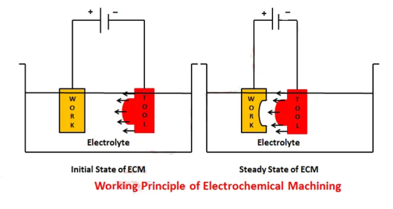
The electrochemical or galvanic coating or deposition process is the polar opposite of ECM operation.
The reactions occur at the electrodes, namely the anode (workpiece) and cathode (tool), as well as within the electrolyte, during the electrochemical machining process.
Consider the case of machining low carbon steel, which is primarily made up of ferrous alloys (Fe). To process ferrous alloys, we often employ a neutral salt solution of sodium chloride (NaCl) as the electrolyte. In the electrolyte, the ionic dissociation of NaCl and water occurs as indicated below.


When a potential difference is applied across an electrode, ions begin to travel between the tool and the w/p. Positive ions are drawn to the tool (cathode), while negative ions are drawn to the workpiece.
The Electrochemical Process
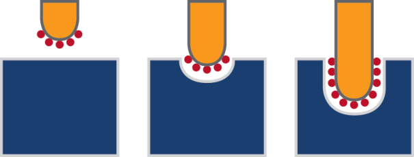
The way material is removed from the workpiece in the electrochemical process is rather distinctive. The electrochemical reactions occur at the anode (workpiece) and cathode (tool), as well as in the electrolyte fluid surrounding them. Ions flow between the tool and the workpiece as an electrical current is delivered across the electrode. Positive ions move towards the tool in electrochemical machining, while negative ions flow towards the workpiece. Electroplating is the polar opposite of this.
Metal ions are ejected from the workpiece as electrons pass the space between it and the tool. Metal hydroxides are formed when these ions interact with hydroxyl ions and are transported away by the electrolyte solution. As a result, the workpiece is smooth and polished, with the desired material removed to achieve the required shape.
Benefits of Electrochemical Machining
Electrochemical machining has a number of advantages that make it an excellent option for machining conductive materials.
Because there is no contact between the tool and the workpiece and no residual stress forces are formed, electrochemical machining delivers an outstanding mirror surface finish that requires no further polishing. Because there is no contact and friction between the tool and the workpiece, less heat is generated during the machining process. It's also feasible to cut small and detailed work in hard or unique metals, such as titanium aluminides or high nickel, cobalt, and rhenium alloys, at high metal removal rates.
With the correct convex and concave tools, you may quickly create complex concave and curved workpieces.
Drawbacks of Electrochemical Machining
Despite its many advantages, electrochemical machining has certain disadvantages. A salty or acidic electrolyte might make the tool, workpiece, or equipment more prone to corrosion. A significant initial investment and significant electrical running costs are also required for an electrochemical machining setup. Finally, conductive materials are the only ones that can be machined. Electrochemical machining, on the other hand, provides a highly valuable option for precision machining of some materials that are normally very difficult to mill.
When conventional machining isn't an option, electrochemical machining is often utilised as a last resort. The reason for this is because it is a lengthy procedure.
3.5.1 Electrical Discharge Machining (EDM): Parts, Working Principle, Advantages, Disadvantages & Applications.
Spark Machining or Spark Eroding is another name for the Electrical Discharge Machining method.
As you may be aware, there are a variety of non-traditional machining technologies available, with EDM being one of them. The others are listed below.
• Ultrasonic Machining (Ultrasonic Machining)
• ECM (Electrochemical Machining)
• Machining with a water jet
• Machining with an abrasive water jet
• Electron Beam Machining (Electron Beam Machining)
• Machining Using a Laser Bea
• EDM (Electrical Discharge Machining)
Let's take a closer look at the Electrical Discharge Machining Process.
Electrical Discharge Machining Definition:
Electric Discharge Machining is a procedure in which electrical energy is utilised to generate a spark between the tool and the workpiece that is submerged in a dielectric media, allowing material to be removed from the workpiece's surface by local melting or vaporisation.
Electrical Discharge Machining Diagram:
The diagram of Electrical Discharge Machining is shown below.

Parts of Electrical Discharge Machining:
The Electrical Discharge Machining (EDM) setup consists of
Pulse Generator No.
1 (Power Supply)
2. Workpiece
3. Fixture
4. Dielectric Fluid No
5. Pump
6. Filter
7. Tool Organizer
8. Creating a spark
9. Tool
An Explanation for the parts of Electrical Discharge Machining:
An Explanation for the parts of Electrical Discharge Machining is as follows.
1. Pulse Generator (Power Supply):
The EDM process is powered via a negative terminal connected to the tool and a positive terminal connected to the workpiece.
2. Workpiece
A fixture is used to secure the workpiece in the dielectric container, and the positive terminal of the power supply is connected to it.
3. Fixture:
In a dielectric container, the fixture is utilised to hold the workpiece in place.
4. Dielectric Fluid:
The workpiece and the tool are separated using dielectric fluid, and the distance between them is kept as small as possible.
The dielectric fluid acts as an insulator under normal circumstances. In this sense, there is no electrical conductivity.
However, when high pressure is applied, the dielectric fluid ionises into Negative and Positive Ions, allowing it to conduct.
Properties of the Dielectric Fluid/Medium:
1. It has a low viscosity, for starters.
2. Maintain electrical non-conductivity until the required voltage is reached.
3. It can be utilised to keep you cool.
4. It is capable of transporting all metal particles produced by spark erosion.
Electrolyte used:
Kerosene acts as a Dielectric Fluid in Electrical Discharge Machining process
Optimum Gap:
The Optimum gap between the tool and the workpiece is 0.03 mm.
Voltage - 70V
5. Pump:
A pump is utilised to transport the dielectric fluid from the container's base to the tool and workpiece, resulting in increased MRR.
6. Filter:
To remove any abnormalities or dust particles in the dicentric medium, a filter was placed slightly above the pump.
7. Tool Holder:
It is used to hold the tool properly.
8. Spark generation:
In the presence of a dielectric medium, a spark is generated between the tool and the workpiece, resulting in material removal from the workpiece's surface.
9. Tool:
Copper, Tungsten, or Copper-Tungsten Alloy are the tools used in the Electric Discharge Machining process.
The Tool's Unique Qualities:
It must have a high level of performance.
1. Melting Point
2. The ability to conduct electricity
MRR (Material Removal Rate):
Electric Discharge Machining will remove the most material of all the non-traditional machining procedures. In this regard, EDM has a higher MRR.
This is how the EDM sections are explained. Let's take a look at how it works.
Working Principle of Electrical Discharge Machining Process:
A fixture secures the workpiece in the dielectric container.
The Servo Feed Unit, which can move downward in a vertical direction, feeds the tool.
The electrical discharge machining technique is powered by a positive terminal connected to the workpiece and a negative terminal connected to the tool.
The tool and workpiece are separated using dielectric fluid, and the distance between them is kept as small as possible.
As previously established, the dielectric fluid acts as an insulator under normal conditions. In this sense, there is no electrical conductivity.
The dielectric fluid, however, ionises into Negative and Positive Ions when sufficient pressure is applied
Positive ions attract negative ions, while negative ions attract positive ions, resulting in the generation of heat.
When positive and negative ions clash, a spark is created between the tool and the workpiece, allowing the material to be removed off the workpiece's surface.
When there isn't a spark in the container, the dielectric fluid acts as an insulator once more.
To remove the material off the workpiece's surface, the same method is used.
This is a comprehensive overview of the Electrical Discharge Machining process, including terminology and how it works.
Advantages of EDM:
These are some advantages of using Electrical Discharge Machining:
1. The machining process is independent of the workpiece's mechanical qualities.
2. Because no forces are acting, no residual stresses will be created.
3. The deeper hole has the potential to produce up to 20 (L/D).
4. EDM has the highest Material Removal Rate of all the non-traditional machining processes (MRR).
5. Melting and vaporisation improve the surface finish.
Limitations of EDM:
However, EDM has some limitations too, here are those:
1. The material used for the workpiece must be electrically conductive.
2. It is impossible to make perfect square corner holes.
3. The hardening of the workpiece occurs near the hole.
Applications of EDM:
Here are some applications of Electrical Discharge Machining:
1. It is used to create holes with a diameter of less than 0.1 mm.
2. Used in the sinking or manufacture of dies.
3. An electrical discharge machining procedure was used to drill holes in the air brakes or pneumatic brakes.
So that's all there is to Electrical Discharge Machining; I hope you enjoyed it; if so, please share your ideas in the comments area, and please share this information with your friends.
3.6.1 What is Wire Edm?
Wire Electrical Discharge Machining (Wire EDM) can be used to create features that would be difficult or impossible to obtain using traditional methods, such as microscopic slots, square corners, and complex geometrical shapes. The method can be utilised on hard materials and provides a higher level of positional precision. This is owing to the machine's near-zero cut force, which permits linear motors to be used instead of traditional ball screws.
WIRE EDM METHOD
Wire EDM is a process whereby a thin wire is used as an electrode to cut along a programmed path. The workpiece is submerged in a dielectric fluid (which increases the water’s resistivity) allowing for the generation of an arc at the wire, which in turn disintegrates the workpiece. The machine uses a spool of wire that moves continuously to offer a fresh section of wire throughout the cutting process, this results in an incredibly repeatable process.
Advantages Of Wire EDM
Wire EDM has the following advantages:
1. Excellent surface finish
2. High level of precision
3. Enables the machining of features that would be extremely difficult or impossible to machine using traditional methods.
4. Suitable for rare and tough materials (Conductive only)
5. Access to interior features can be gained by threading wire through a pre-existing pilot hole.
Disadvantages Of Wire EDM
The disadvantages of Wire EDM include:
- The wire must pass through the entire part which means this process is not suitable for ‘blind-hole’ applications
- The process can be time-consuming depending on the amount of material to be removed
- Brass deposits can be found on the part post-machining
- The tighter the tolerance the more cuts required to hold – Each pass results in additional processing time
PCML’S Wire EDM Services
Here at PCML, we offer the following Wire EDM services:
- We have invested in four CNC Wire EDMs offering a 0.05mm – 3.0mm electrode diameter and a maximum taper angle of ±20° (generated using U and V Axis).
- Sodick AG600L – X600 x Y400 x Z350
- Sodick AQ325L – X325 x Y250 x Z200
- Excetek V350G – X350 x Y250 x Z220
- Excetek V650G – X605 x Y400 x Z350
- K1C Hole Driller – used for putting in start holes for WEDM, drilling exotic materials, angular drilling and removing broken tooling to a maximum hole depth of 200mm (Styluses range from 0.25 – 3.0mm) PCML current styluses 0.3, 0.6, 0.8, 1.2, 1.5, 2.0, 2.4, 3.0mm
These devices are capable of handling pieces weighing up to 1,000 kilogrammes. Our highly skilled engineers oversee each job to guarantee that all parts are delivered to the stringent standards demanded by the PCML Group and our customers.
A Brief Bit of EDM History
Joseph Priestley’s observations in 1770 led to the development of the electrical discharge machining (EDM) method that we know today. In his investigations, he observed that electrical discharges had stripped material from the electrodes. Electro-discharge erosion is another name for this.
The Lazarenkos, two Soviet researchers, invented a machining process in the 1940s that laid the groundwork for modern wire EDM and small hole EDM.
Spark machining, spark eroding, and die sinking are all terms used to describe EDM.
How Electrical Discharge Machining Works
The basic electrical discharge machining procedure is relatively straightforward. Between an electrode and a workpiece, an electrical spark is formed. The movement of electricity is apparent in the form of a spark. This electric spark generates enormous heat, ranging from 8000 to 12000 degrees Celsius, capable of melting practically anything. The spark is precisely regulated and focused so that it only touches the material's surface. The heat treatment underneath the surface is largely unaffected by the EDM procedure. The spark always happens in deionized water's dielectric. The water's conductivity is carefully managed, creating an ideal environment for the EDM process. The water cools the machine and flushes the corroded metal particles away.
3.7.1 Abrasive Jet Machining – Process, Parameters, Equipment, MRR.
Abrasive jet machining (AJM) is a mechanical energy-based advanced machining method that uses a high-velocity jet of abrasives to remove material from a work surface by impact erosion. Fine abrasive particles are accelerated in a highly pressured gas to produce the abrasive jet (carrier gas). A nozzle is used to transform the pressure energy into kinetic energy and to aim the jet at a specific angle towards the work surface (impingement angle). When hard abrasive particles collide, they gradually remove material by erosion, which is often aided by brittle fracture.
The possible level of accuracy and precision distinguishes AJM from traditional sand blasting techniques. Alumina, silicon carbide, glass beads, sodium bicarbonate, and other abrasives are used in AJM, whereas silica sand is used mostly in sand blasting (SiO2). Although the goals of both techniques are similar, AJM allows for more precise control of cutting parameters, resulting in greater accuracy and precision.
Abrasive particles used in abrasive jet machining
Hard abrasive particles are thought to engage in material removal in AJM, whereas carrier gas helps to blow away eroded particles from the machining zone. For efficient material removal and optimum cut quality, such abrasives must contain a few basic qualities. Sufficient hardness, irregular shape, sharp edges, and good flow characteristics are all desirable attributes.
Depending on the workpiece material and the operation to be performed, different abrasives with a variety of grit sizes might be used. For grooving and drilling operations, aluminium oxide (alumina) with an average grit size of 10 – 50m is widely employed, especially when the work material is hard. However, because silicon carbide (SiC) is tougher than alumina, it is recommended for particularly demanding work materials. Glass beads and shattered glass are commonly used for polishing and coating removal. The size of the abrasives has an impact on both the quality of the cut and the pace of material removal. Because bigger grit sizes yield larger cavities, MRR improves at the expense of surface quality. Fine abrasives, on the other hand, lower MRR while improving surface quality and precision.
Carrier gas for abrasive jet machining
In abrasive jet machining, the primary function of the carrier gas is to accelerate fine abrasive particles (by momentum transfer). A compressor raises the carrier gas's pressure (to as high as 20bar); abrasive grits are combined with it in a mixing chamber (according to the mixing ratio); and a nozzle converts pressure energy into kinetic energy (in the form of high velocity jet). Final jet velocity and consequently machining performance are determined by carrier gas pressure and nozzle diameter.
Air is one of the most widely used gases in AJM since it is abundant and free. Commercially pure carbon di-oxide and nitrogen are sometimes utilised to improve performance for a specific purpose. Pure oxygen, on the other hand, is not used since it might quickly oxidise the work surface. Because steam might clog pipelines, carrier gas is thoroughly dehumidified before compression. When a gas is squeezed to a high pressure, steam condenses, and microscopic water particles agglomerate with abrasives to form a bigger globule. Before compressing to high pressure, the carrier gas is also rendered dust-free.
Nozzle used in abrasive jet machining
In abrasive jet machining, the primary function of the nozzle is to transform the pressure energy of the pressurised gas-abrasive combination into kinetic energy in the form of a high-velocity jet. In addition, the nozzle drives a high-velocity jet onto the work surface from a set distance (called SOD) and at a predetermined angle (called impingement angle). The nozzle's inner diameter is a critical parameter since it influences the jet's final velocity and cross-sectional area for a given gas pressure. Jet velocity will be inversely proportional to jet cross-sectional area if the flow rate and compressor supply pressure remain constant.
From an economic standpoint, the material of the nozzle is also important. In industrial applications, tungsten carbide (WC) or sapphire nozzles are typically employed. WC nozzles are less expensive but have a shorter lifespan (20–30 hours), whereas sapphire nozzles have a longer lifespan (150–200 hours) but are more expensive. Idle time during milling is linked to frequent nozzle changes.
Equipment for abrasive jet machining
Air compressor: The carrier gas is compressed to a pressure of 15–20bar. Drier and filter are also included in the compressor unit. To reduce condensation or jamming during compression, it eliminates water vapour and dust particles.
Pressure gauges: Several of these gauges are used to measure the pressure of the carrier gas as well as the gas-abrasive mixture.
Flow regulating valves: These valves regulate the volume flow rate of carrier gas in order to keep the mixing ratio constant.
Hopper: In AJM, a circular hopper with gradual compression is typically used to provide fresh abrasive to the mixing chamber on a constant basis. To avoid bridging, the hopper is occasionally vibrated (jamming at outlet).
Mixing chamber: Its job is to combine abrasives with a pressurised carrier gas. Momentum is transferred here, and abrasives begin to flow with carrier gas. To achieve homogenous mixing, the chamber is vibrated.
Nozzle: As an isentropic steady flow device, nozzle converts hydraulic energy (pressure) of the gas-abrasive mixture to the kinetic energy and thus high velocity jet is obtained.
Working chamber: To avoid environmental pollution, a close working chamber with a good exhaust system is normally maintained. It also aids in the protection of workers from lung diseases caused by exposure to an environment containing an excessive amount of fine abrasive particles.
Servo controller: Servo mechanisms are sometimes used to control the movement of the work table. This allows for simple, accurate, and exact control when cutting difficult profiles and shapes.
3.7.2 Process parameters and their influence on AJM:
Abrasive jet machining performance is influenced by a variety of factors. The shape, size, strength, material, and flow rate of abrasive particles; the nature, composition, flow rate, pressure, and temperature of carrier gas; the mixing ratio, striking velocity, impingement angle, and stand-off distance of the abrasive jet; the profile and inner diameter of the nozzle; and the mechanical properties and stress concentration of the work material are all important process parameters.
AJM performance is usually assessed by analysing three output responses, namely (i) material removal rate (MRR), (ii) surface roughness and accuracy of machined feature, and (iii) nozzle life or nozzle wear rate. Effects of process parameters on AJM performance are discussed below.
Input and Output parameters in AJM | |
Process parameters | Output responses |
1. Abrasive particles – its shape, size, strength, material and flow rate. | 1.Material Removal Rate (RR) |
2. Carrier gas-its nature, composition, flow rate, pressure and temperature. | 2. Surface roughness and accuracy of machined feature. |
3. Abrasive jet –mixing ratio, striking velocity, impingement angle and stand-off distance | 3. Nozzle life or nozzle wear rate. |
4. Nozzle- its profile and inner diameter. |
|
5. Work material-its mechanical properties and stress concentration |
|
Effects of abrasives on AJM performance
As previously stated, abrasive shape, size, strength, substance, and flow rate can all affect machining performance. When compared to spherical grits, irregular shape abrasives with sharp edges create higher MRR. Smaller grits produce a more polished surface, but they slow down the material removal rate (MRR), lowering productivity. Larger grits might cause problems in the pipeline when mixing and flowing. However, there should be little change in size across the entire volume; otherwise, estimation or judgement will be inaccurate.
Abrasive materials come in a variety of strengths and hardness. The larger the volume removal rate, the harder the abrasive is in comparison to the work surface hardness. Machining capabilities and productivity are largely determined by the relative hardness of the abrasives and the workpiece. Mixing Ratio, whose effects are also covered later in this section, is frequently used to manage the mass flow rate of abrasive.
Effects of carrier gas on AJM performance
The pressure and flow rate of the carrier gas are two critical elements that influence performance and machining capability. Higher gas pressure lowers jet spreading, allowing for more precise cutting of deeper slots. Various accessories, including the pipeline, must, however, be able to withstand such high pressure without failing. Furthermore, a larger gas flow rate allows for the use of a greater abrasive flow rate, which can boost productivity.
Effects of mixing ratio on AJM performance
The mixing ratio (M) is the proportion of abrasive particle mass flow rate to carrier gas mass flow rate. It basically determines the abrasive concentration in the jet. By raising the abrasive %, the mixing ratio can be raised, and an upward trend in MRR may be seen because a larger number of abrasives participate in micro-cutting activity per unit time. However, because of lower jet velocity (due to constant gas pressure) and inevitable collisions, an excessive concentration of abrasive in the jet can dramatically diminish MRR (thus loss of kinetic energy).
MRR can be improved by proportionally raising both the abrasive and gas flow rates at the same time while keeping the mixing ratio constant. In this situation, the carrier gas must be used at a higher pressure. To manage such high pressure without leakage or rupture, thicker and stronger pipelines and other accessories are required. Because of the restricted capability of equipment and accessories, an indefinite growth in MRR is not viable.
Effect of stand-off distance on AJM performance
Stand-Off Distance, abbreviated as SOD, is the distance between the work surface and the tip of the nozzle in an abrasive jet machining setup. Higher SOD causes the jet to spread, increasing its cross-sectional area at the expense of jet velocity. As a result, machining deeper slots or holes becomes more difficult, therefore a larger area is cut instead. Smaller SOD, on the other hand, can cut a deeper but narrower groove or hole. It also boosts MRR. As a result, an optimal stand-off distance must be determined in order to get satisfactory results in abrasive jet machining.
Effect of impingement angle on AJM performance
Impingement angle (), also known as spray angle or impact angle, is the angle formed by the work surface and the axis of the abrasive jet. In order to achieve satisfactory results in AJM, it is usually kept between 60o and 90o. A larger angle results in deeper penetration, whereas a lesser angle results in more machining area. In abrasive jet machining, an impingement angle () of 70o – 80o produces superior results in terms of material removal rate.
Material removal rate and its estimation
The material removal rate (MRR) is important to know when choosing process parameters and nozzle feed rates. It also makes precise estimates of productivity, delivery time, and production cost possible. Because only abrasive grits' kinetic energy is used for erosion, the analytical formula for MRR may be calculated by equating available kinetic energy with the work necessary to create an indentation of a given cord length on a given work material.
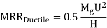
However, ductile and brittle materials behave differently in indent creation, and hence the size of the indentation formed by a single abrasive grit differs between the two. MRR for abrasive jet machining of various materials can be analysed analytically and represented as shown below under a few assumptions.
Expression of MRR for ductile and brittle materials in AJM

Process capability of abrasive jet machining
• Materials: Preferably hard and brittle materials.
• Surface finish: 0.10m can be achieved.
• 0.10mm tolerance
• Minimum feature size is 0.10mm.
• Minimum corner radius is 0.2mm.
• The MRR is 15 mm3/min.
• Plate thickness varies from 2 to 6 mm depending on the material.
Advantages of abrasive jet machining
• Surface deposits may be removed;
• a wide range of surface finishes can be achieved;
• the process is not affected by electrical or thermal attributes
• There is no thermal damage to the workpiece.
• Suitable for brittle nonconductive materials
• Low initial capital outlay
Disadvantages of abrasive jet machining
• Soft and ductile materials are not suited.
• Abrasives are not reusable;
• Collection and disposal of abrasives are difficult
• Cutting and drilling that isn't precise (stray cutting)
• Nozzle life is limited.
Applications of AJM
Abrasive jet machining can be advantageously utilized for multifarious purposes including surface cleaning, deburring, abrading and even making holes. Common applications of abrasive jet machining process are provided below. It is to be noted that, irrespective of the purpose, abrasive jet machining (AJM) is beneficial only for hard and brittle materials. AJM should be avoided if work material is soft and ductile; otherwise, quality of machined surface will be poor.
- Work surface cleaning— Cleaning metallic or ceramic surfaces with AJM is a good idea (substrate must be hard). Removal of oxide, paint, varnish, stain, adhesive, loose sand particles, and other contaminants are among the cleaning methods.
- Deflashing and trimming— Controlled abrasive jet machining can be used to remove flash, resulting in a clean product with improved dimensional precision and tolerance, as well as a rich appearance.
- Engraving— Abrasive jet machining can be used for incising purposes instead of laser beam machining, regardless of the chemical and electrical properties of the work material.
- Ceramic abrading and glass frosting— Glass, refractory, stone, and other hard materials can be easily abraded by AJM to provide a finished surface with tight tolerance.
- Deburring— Deburring machined features and drilled holes with abrasive jet machining is one of the most efficient processes for removing burrs, especially when the work material is hard.
- Cutting and drilling hole— AJM may also be used to cut a variety of forms as well as drill holes. However, because this method does not produce precise corners, holes, slots, or pockets may be inaccurate.
References:
- Book: Non-traditional Manufacturing Processes by G. F. Benedict (Manufacturing Engineering and Materials Processing-19).
- Book: Unconventional Machining Processes by T. Jagadeesha (I. K. International Publishing House Pvt. Ltd.).
- Book: Advanced Machining Processes by V. K. Jain (Allied Publishers Private Limited).
- Book: Nonconventional Machining by P. K. Mishra (Narosa Publishing House).
- Paper: M. W. Chastagner and A. J. Shih, Abrasive Jet Machining for Edge Generation, Transactions of NAMRI/SME, Volume 35, 2007.


