Unit - 4
Types of Cross-Drainage (CD) Works
a) Pipe aqueduct
b) Box culvert/irrigation slab drain
c) Masonry aqueduct
d) Siphon aqueduct
e) Siphon culvert
f) Irrigation culvert
2. Super Passage
3. Level Crossing
4. Inlet and Outlet
1. Aqueduct:
It is irrigation structure constructed for passing canal water over the drainage work.
An aqueduct consists of masonry or concrete trough of rectangular section supported on abutment and piers and stream flows below the trough through abutment and piers.
Aqueduct should align normal to the canal and under the following situation an aqueduct is constructed.
(1) When discharge of stream is more as compared to discharge through canal.
(2) And sufficient clearance is available i.e., bed level of canal is at higher level than high flood level of stream.
Aqueduct is further classified as follows:
Classification of Aqueduct
(1) Pipe aqueduct
(2) Box culvert
(3) Masonry aqueduct
(4) Syphon aqueduct
(5) Syphon culvert
(6) Irrigation culvert
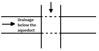
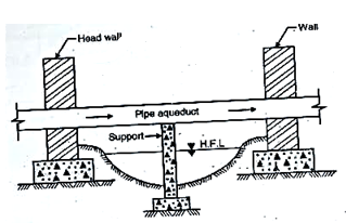
(1) Pipe aqueduct:
In this case canal water is taken through pipe. In the pipe aqueduct the diameter of pipe depends on discharge. It is adopted when-canal section is very small and width of drain is more.
Sometimes a trough is divided into two compartments and second compartment is covered with slab which is later useful for roadways.
(2) Box culvert:
The culverts are similar to ordinary bridges only difference is that the road is replaced by canal. Culverts are provided under following situation.
When stream discharge is less as compared to canal discharge. In culverts thickness of slab is generally 30 to 50 cm.
It consists of abutment of UCR or concrete and piers according to necessity.
(3) Masonry aqueduct:
In this type of aqueduct, it is constructed with masonry and the width of drainage is very large and drain water passes through it.
Roadway is provided on one side of canal and inspection path on other side Wing walls are also provided on upstream and downstream side.
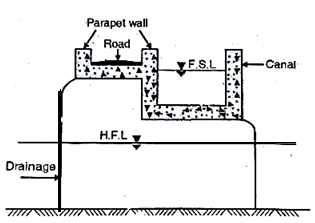
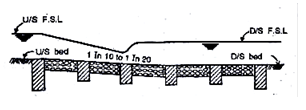
(4) Syphon aqueduct:
When HFL of the drainage is above or touches CBL (Canal Bed Level) but lower than FSL and drainage is small this type of aqueduct is preferred.
In this type canal is at higher level than the drainage.
It consists of pipe aligned normal to the canal at sufficient depth below CBL. The canal is flumed and taken cross through trough.
The water flows under hydrostatic pressure through this depression in order to avoid deposition of silt a small slope is provided to give self-cleaning velocity.
(5) Syphon culvert:
n this type of culvert the bed of drainage is depressed. These are not preferred if discharge through drainage is more.
(6) Irrigation culvert:
This culvert belongs to class of cross drainage work. These are located at nallaha, stream, torrent, river where it crosses the canal alignment. These are preferred when width of drainage varies from 2.5 to 16 m. Arched roof is provided instead of RCC slab.
2. Super passage:
It is structure constructed at point of crossing where drainage water is taken over the canal. In this case stream passes at higher level than FSL of canal
The main object of super passage is to take stream discharge safely across canal and at higher level.
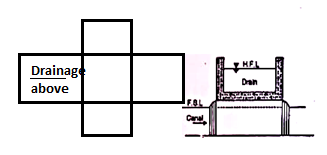
In this case stream passes over the canal through masonry trough which is supported on supporters. (i.e., abutment, piers etc.) Stream is always flumed by providing suitable wing wall
Super passage is classified as follows as:
(1) Pipe super passage
(2) Syphon super passage
(1) Pipe super passage:
In this case pipe is provided for carrying drainage water over the canal. Pipe super passage is provided only if discharge is less. The main disadvantage of these type of super passage is that if silt is deposited it is difficult to clear it off
(2) Syphon super passage:
In this type the bed of canal is depressed so that FSL should not touch the root of water way
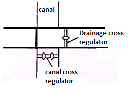
3. Level crossing:
This type of cross drainage work is adopted when bed level of canal and drainage is same.
In this case both water allows to mix with each other. The regulators are provided on downstream side of drainage and canals to regulate discharge. Regulators are provided with lift gates.
In order to protect bed from eroding action suitable stone pitching is provided on bed and sides of canal on upstream and downstream side.
During dry season downstream drainage regulator is kept closed and canal regulator is kept open so that canal water flows smoothly and during floods drainage regulator is opened to pass flood water.
4. Inlet and outlet:
Inlet admits water of stream into the canal and it flows mixed with canal water and then excess discharge is allow to pass through outlet.
The capacity of inlet and outlet must be same and sides and beds of canal must be protected by stone pitching.
Key takeaways:
Following are the points which show the design consideration of C. D. Works.
(i) Fixation of waterway of the drain.
(ii) Computation of maximum flood discharge and High Floor Level (HFL).
(iii) Consideration of clearance and free board.
(iv) Contraction of canal waterway for the type III aqueducts.
(v) Consideration of head loss through syphon barrels.
(vi) Design of bank connections.
(vii) Computation of uplift pressure on the roof of trough and on the floor.
Key takeaways:
1. Diversion head work:
A diversion head work is a structure constructed across a river so as to raise water level on upstream side so that it can be diverted towards canal.
These are constructed on river where adequate flow of river water is available throughout the year.
If the storage on upstream of diversion head work is significant, it is called storage weir and if it is constructed on downstream of dam for purpose of diverting water from upstream side of dam into canal, it is called pick up weir.
Location of Diversion Head Work:
The location of diversion head work should be near to command area. The site which gives most economical arrangement is usually selected.
Function of Diversion Head Work:
1. Diversion head works regulates the flow of water into canal.
2. It increases the level of water in the river or streams.
3. Due to increase of the level of water and thus increases the command area for irrigation.
4. It does not allow the entry of silt, gravels into canals and thus control the entry of slit, gravels into the canal.
5. It helps in regulating the supply of water into canals.
6. It helps in controlling the vagaries of the river and streams.
7. It creates a small pond act as a short storage pond for a small period on its u/s and thus provides some pondage.
8. It minimizes the fluctuations in the level of supply in the river or streams.
9. It increases the water level on its u/s side.
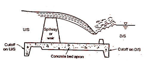
2. Types of weirs and barrages
A structure constructed across river to raise water so as to divert this raise water into canal and this raising of water is mostly done by the crest wall constructed across river and very small part or nil part is by shutter sometimes if provided on its top is called as weir and when (most water stored) storing of water is done by gates or shutters and small part or nil part of water is by the raised crest then such structure constructed is known as barrage.
In weir affluxes caused is more during high floods while in barrages afflux is nil or minimum as flow of water is controlled by shutters during floods ges are opened and thus afflux is controlled.
Types of Weirs
(1) Gravity weir
(2) Non gravity weir
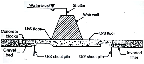
(3) Vertical drop weir
(4) Rock fill weirs
(5) Concrete weirs
(1) Gravity weir:
When the weight of weir balances uplift pressure caused by the head of water seeping below weir it is called as gravity weir.
(2) Non gravity weir:
In non-gravity weir the uplift pressure is largely resisted by weight of concrete slab with the weight of divide pins.
Gravity weirs are further divided into following types:
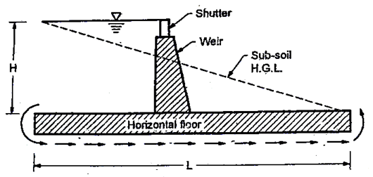
(1) Vertical drop weir: This type of weir consists of horizontal floor and a masonry crest with vertical or nearly vertical downstream face and the shutters are provided at the crest.
Most of storage is done by raised crest and some storages by chatters provided over the crest
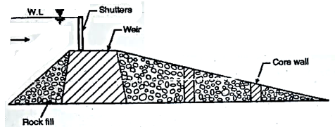
(2) Rock fill weir
It is also called as dry-stone slope weir. It is suitable for fine sandy foundation stone are mainly used for construction of such type of weir and hence requires large quantities of stone.
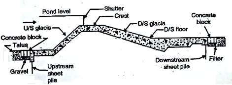
(3) Concrete weir.
These are suitable for permeable foundations. In such weirs sheet piles are provided on both upstream and downstream floors, in order to destroy the energy of water.
3. Layout of a diversion head works
1) Storage weir
It is high weir constructed for storing water. It is also called as diversion weir. In such weir’s shutters may or may not be provided.
2) Pick up weir
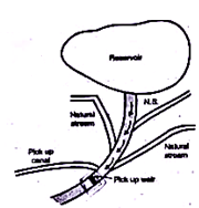
These are constructed when command area is far away from reservoir either due to rolling topography or because the land is not cultivable and if there is broken or rolling topography on one or both banks of river in which construction of canal may be costly.
In pick up weir water from main storage is released and carried through same river up to pick up weir from which it is diverted into canal for irrigation purpose.
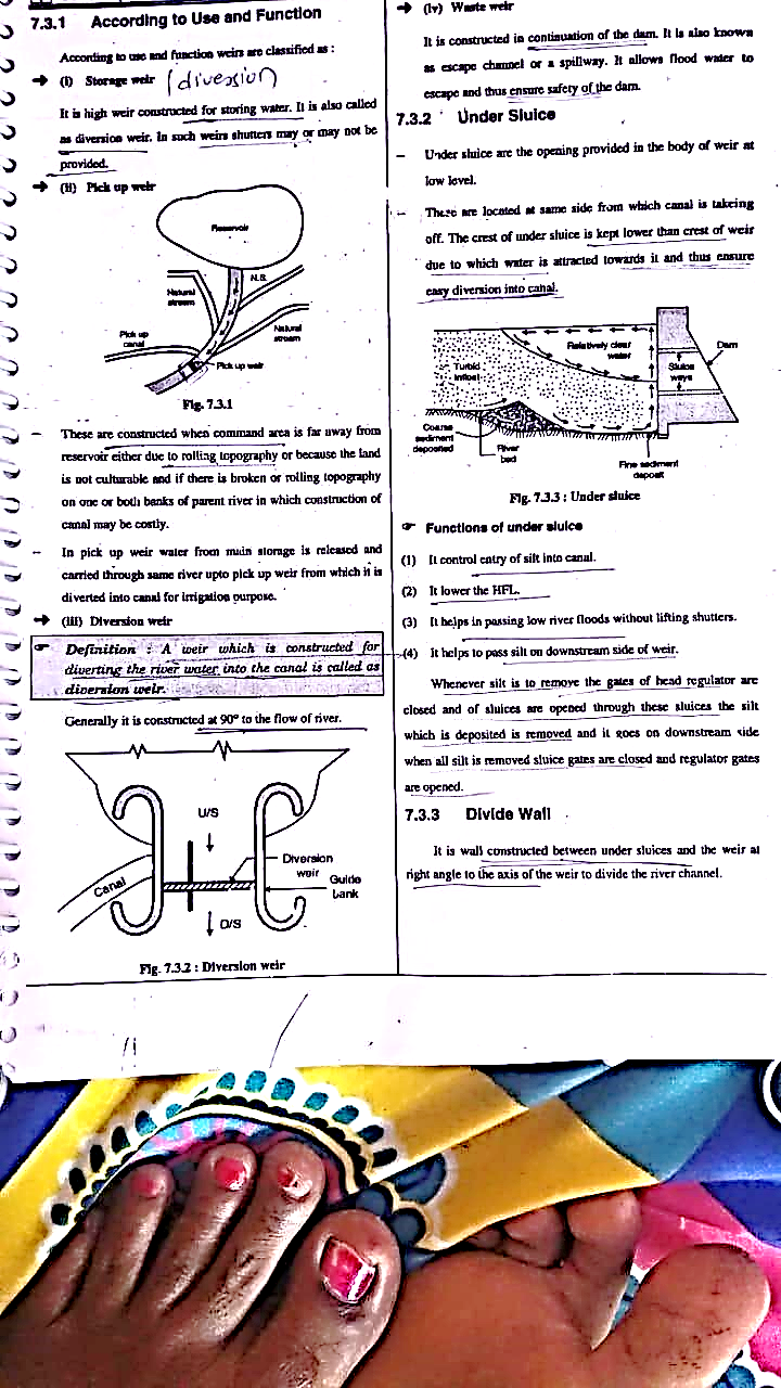
3) Diversion weir
A weir which is constructed for diverting the river water into the canal is called as diversion weir.
Generally, it is constructed at 90° to the flow of river.
4) Waste weir
It is constructed in continuation of the dam. It is also known as escape channel or a spillway. It allows flood water to escape and thus ensure safety of the dam.
5) Under Sluice
Under sluice are the opening provided in the body of weir at low level.
There are located at same side from which canal is taking off. The crest of under sluice is kept lower than crest of weir due to which water is attracted towards it and thus ensure easy diversion into canal.
Functions of under sluice
(1) It controls entry of silt into canal.
(2) It lowers the HFL.
(3) It helps in passing low river floods without lifting shutters.
(4) It helps to pass silt on downstream side of weir.
Whenever silt is to remove the gates of head regulator are closed and of sluices are opened through these sluices the silt which is deposited is removed and it goes on downstream side when all silt is removed sluice gates are closed and regulator gates are opened.
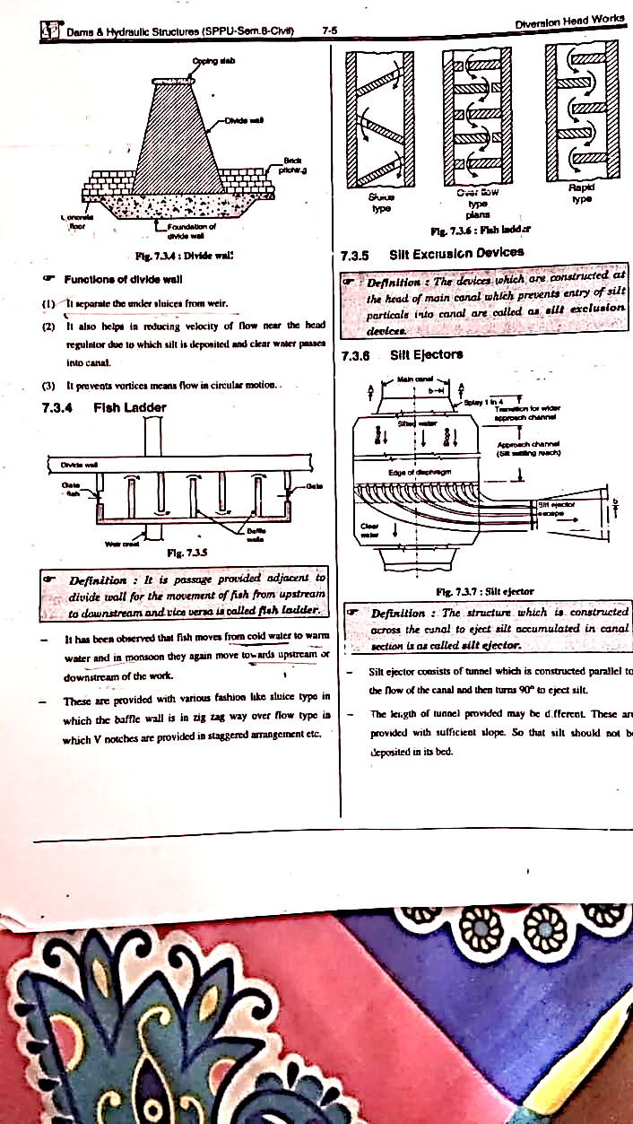
6) Divide Wall
It is wall constructed between under sluices and the weir at right angle to the axis of the weir to divide the river channel.
7) Fish ladder
It is passage provided adjacent to divide wall for the movement of fish from upstream to downstream and vice versa is called fish ladder.
It has been observed that fish moves from cold water to warm water and in monsoon they again move towards upstream or downstream of the work.
These are provided with various fashion like sluice type in which the baffle wall is in zigzag way over flow type in which V notches are provided in staggered arrangement etc.
8) Guide Bank
Guide banks are provided on either side of diversion head work in alluvial soil to prevent river from out flanking the work.
The main object of guide banks are
(1) It prevents oblique approach to the head regulator.
(2) It protects regulator from river attack.
(3) It increases maximum discharge at all point.
(4) It prevents out flanking of structure.
(5) I create reasonable water way for a weir.
9) Marginal Embankment
Marginal embankment is provided on either bank of river upstream of diversion head work to protect the land and property which is likely to be submerged during flood.
Marginal embankment helps in
(1) It increases the intensity of flood.
(2) It increases bed level of the river by silting.
(3) It protects land and property which is likely to be submerged.
Key takeaways:
1. Comparison among Bligh’s creep theory:
The length of the seepage path creeps into the foundation la called as ereep length (L).
2. According to Bligh, there is no distinction between the creep in the horizontal direction below the floor and in the vertical direction along the faces of the profile.
3. Loss of head per unit length of creep is constant throughout the path of seepage.
4. If H total loss of head and L Total creep length of seepage, then loss of head per unit length is equal to H/L
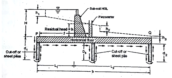
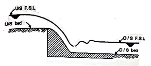
5. Fig. shows a weir with a horizontal floor of length L. Weir is subjected to a seepage head H
So as the rise the percolation path of water's cut-off or sheet piles are provided as shown in Fig.
6. According to Bligh, there is horizontal and vertical creep path of percolation in the same sense.
Total creep length (L) = (2d, +L, + 2d, + L₂ + 2d₂).
Where d. d, and d, are the depths of the u/s, d/s and intermediate cut off or sheet piles respectively L, and Ly are the length of us and d/s floors.
7. Sub-soil hydraulic gradient is given by the expression as, follows:
H (2d, + L₁ +2d, +L₂ + 2d₂)
8. As the water moves in a vertical path, there is for taken place in the vertical plane at the same section and this loss is proportional to the length of the vertical path.
Loss of head = H /L x 2d₁ and it takes place in its
For cut-off d₂, loss of head. For cut-off d, loss of head = H / Lx2d₂
Residual head (h) = H-H/L (2d₁+1)
B. Bligh also suggests the design criteria for the safety of a weir against:
(i) Piping failure
(ii) Uplift pressure
Limitations of Bligh's Theory
1) No differentiation between the vertical creep and horizontal creep. Bligh gives the same importance to both.
2) Head loss variation is linear but actual head loss variation is non-linear.
3) The effect of varying length of cut-off or sheet piles not considered.
4) No distinction is considered between the head loss on outer face and on the inner faces of sheet piles.
5) No theoretical or practical method to find the creep coefficient or the safe gradient.
6) The exit gradient is not considered.
7) Loss of head is considered proportional to the creep length.
8) Actually, it is not correct.
9) Necessity of providing end sheet pile not appreciated.
10) Bligh theory does not give the approximate results if the horizontal distance between the piles is less than twice their depths.
2. Lane’s weighted creep theory
Lane's Theory or (Lane's Weighted Creep Theory)
Lane's theory may also be called as the modified Bligh's creep theory corrected for vertical contacts.
When number of hydraulic structures designed based on the Bligh's creep theory failed because of excessive uplift pressures or undermining.
Lane pointed out the draw-back of Bligh's theory that no distinction was made by Bligh between vertical and horizontal creeps.
Lane noted that the relative resistance to flow along horizontal and vertical creep lengths was only be deduced from a comparison of a large number of existing structures.
Hence Lane studied 278 dams and weirs constructed on different soils with various description and he found that the vertical creep was more effective rather than horizontal creep. From this point of view, he recommended that the horizontal creep lengths should be reduced to of their actual values and suggested that vertical creep length should be used directly.
In short, horizontal creep length is reduced tord of their actual values and there is direct use of vertical creep length. As suggested by lane the horizontal creep is less effective in reducing uplift pressure as compared to the vertical creep.
If N sum of all the horizontal contacts and of all sloping contacts <45° to the horizontal.
V sum of vertical contacts and sloping contacts greater than 45° to the horizontal, then weighted creep length (Lw) is given by the following expression by Lane.
Weighted creep length, Lw= {N+V
It shows the more effective resistance to flow in the vertical direction offered by summered soils.
For safety against piping, "Lw' should not be less than C, H, where C, is the empirical constant depends upon the nature of soil in the foundation.
The empirical constant, C, varies from 1.6 for very hard clay to 8.5 for very fine sand or silt.
Note that the basic concept of average pressure gradients and creep paths remained empirical as in suggested in Bligh's theory.
There are various values of Lane's creep coefficient (C₂) for different types of soils recommended by Lane are shown in tables
Sr. no. | Soil types | Value of lane creep coefficient C1 | Safe hydraulic gradient (1/C1) suggested by lane |
1 | Clayey soil | 3 to 1.6 | 1/3 to 1/1.5 |
2 | Gravel | 3 to 2.5 | 1/3 to ½.5 |
3 | Gravel and sand | 3.5 to 3.0 | 1/3.5 to 1/3 |
4 | Coursed sand | 5.0 | 1/5 |
5 | Fine sand | 7 | 1/7 |
6 | Silt | 8.5 | 1/8.5 |
Sr. No | Lane theory | Bligh’s theory |
1 | Lane observed that vertical creep is more effective than the horizontal creep | Bligh’s made no distribution between horizontal and vertical creep |
2 | Lane’s weighted creep theory is an improvement over Bligh’s theory because if give more weight age to vertical creep | Bligh’s theory does not give more focus or weight age to vertical creep |
3 | According to lanes weighted creep theory an irrigation structure will be safe if the average weighted hydraulic gradient (H/Lw) is less than the safe hydraulic gradient (1/C1) | Bligh’s theory considers the downstream pile only at a component of a total creep length and not as a controlling factor for the exit gradient and the piping |
4 | Lane theory is not accurate and is rarely used in India | Bligh’s theory does not give even the approximate result if the horizontal distance between the piles is less than twice their depth |
Comparison between Lane theory and Bligh’s th
3. Khosla’s method of independent variables
Dr. Khosla suggested the theory of independent variables to determine the uplift pressure at the key points for the structure consisting of a combination of a number of elementary forms such as a horizontal floor, three piles, U/S glacis and Vs glacis.
In the method of independent variable, Dr. Khosis split up, a complicated weir or barrage into number of standard simple forms for which the analytical solution is known.
Uplift pressure is obtained from the at assumption followed by the corrections.
Assumptions
(i) The floor has negligible thickness.
(ii) There is only one sheet pile line.
(iii) The floor is horizontal.
Above assumptions are not satisfied due to an actual profile and hence corrections are applied to the superimposed values of uplift pressure corrections:
(i) Correction for thickness of floor.
(ii) Correction for slope of the floor.
(iii) Correction for the mutual interference of
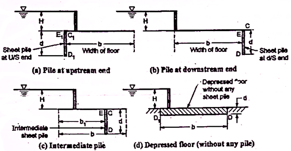
Standard simple elementary profile Following are the various standard elementary forms or profiles suggested by Dr. Khosla Standard elementary form (i) A straight horizontal floor having negligible thickness and sheet pile provided at the downstream end as shown in Fig.
Standard elementary form (ii): A straight horizontal floor having negligible thickness and sheet pile provided at the upstream end as shown in Fig.
Standard elementary form (iii): a straight horizontal floor having negligible thickness with sheet pile provided at some intermediate point as shown in Fig.
Standard elementary form (iv): A straight horizontal floor having thickness (d) depressed below the bed without sheet pile.
Above four case of standard elementary form was studied and analyzed by Dr. Khosla and his associates and derived the standard equations to determine the uplift pressure at the key points such as junction point of she pile and floor, bottom most points of sheet piles and bottom comers of depressed floor and exit gradient.
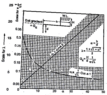
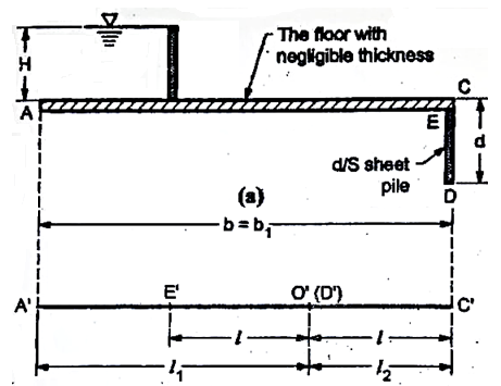
4. Exit gradient
The horizontal floor should be safe against piping: hence to make it safe, the exit gradient should be less than the safe gradient for soil.
For exit gradient for impervious floor with the d/s sheet pile, refer to Fig.
 )
)
 )
)
PC=0
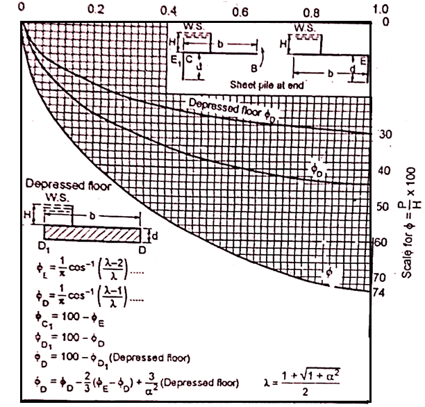
Exit gradient is given by the following equation

The value of exit gradient G can be obtained from the known values of b and d after determining at and A
Khosla's chart as shown in Fig. can be used for the determination of A and from the known values of at and then substitute these values in Equation (1)
Note that the correct curve should be taken for the determination otherwise the value will go wrong.
Note that if floor is not provided by d/s sheet pile or cut-off, d becomes equal to zero and then the exit gradient becomes infinite which do not occur theoretically in actual practice, resulting the a very high value of exit gradient and due to this piping can occur.
Hence it is absolutely necessary to provide the vertical sheet pile or cut-off at the d/s end of the floor which prevents the piping problem.
Sr.no. | Soil type | Safe exit gradient |
1 | Fine sand or silt | 1/6 to 1/7 |
2 | Sand | 1/5 to 1/6 |
3 | Shingle, gravel | ¼ to 1/5 |
Key takeaways:
2. Loss of head per unit length of creep is constant throughout the path of seepage.
3. If H total loss of head and L Total creep length of seepage, then loss of head per unit length is equal to H/L
1. Canal fall:
In a canal, any structure which is constructed to regulate the discharge with a full level or velocity is termed as a regulation work.
There are various types regulation work mentioned as below:
a) Canal fall
b) Head regulator
c) Cross regulator
d) Canal outlet
e) Canal escape
All the type of structures which are constructed to control or to regulate the functions of a canal i.e., full supply level, velocity of flow in the channel are called as the Regulation works.
Such regulation works are necessary for the safety and also for the safely of the channel. Following are some of the important regulation works, which help to keep the working of the channel, efficient and safe:
2. Necessity
A structure constructed across a canal to lower down the water lev. I and vanishes. The surplus energy developed during the falling of water which prevents scouring the bed and banks of the canal is called as fall.
Hence it is very essential to build the fall structure so that scouring of the bed and banks of canal can be avoided.
Location of fall can be decided from the various considerations
3. Proper Location
A structure constructed across a canal to lower down the water lev. I and vanishes. The surplus energy developed during the falling of water which prevents scouring the bed and banks of the canal is called as fall.
Hence it is very essential to build the fall structure so that scouring of the bed and banks of canal can be avoided.
It should be located at such place that there would be no danger of loss of the command area.
It should be such that below the fall, F.S.L. of the channel remains below the ground level for to km, (but, no much more).
This will, not result in any loss of command area, so to that extent the area can be irrigated by the water course from an outlet at high level upstream of the fall.
The location of such fall if is combined with a regulator, or a bridge or any such structure, it becomes economical. i.e., cheap.
It is necessary to see where in that area, where large number of small falls or small number large falls is economical, with the same conditions of not reducing the command area.
For a small length of the channel, in upstream and also in the downstream of a fall, there is unbalanced earth work it should be kept minimum.
For a larger fall, the quantity of unbalanced earth work will be large in volume so the provision of small number of large falls will result in larger quantity of unbalanced earth work so the reduction in the number of falls, will help to reduce the cost of falls. (This saving is to be balanced against the extra cost of earth work, to determine the relative economy).
4. Types:
In the historical period, to avoid the construction of falls, the length of the channel was increased by providing sinuous curves e.g.
It is found in the east Yamuna canal, which was constructed by the Mughal Emperors. This method is not only uneconomical but also has failed to serve the common area efficiently.
The concept of construction of fall was introduced in our country by the British Engineers, in the 19th century. From that onwards, various types of falls have been constructed on the channels in different geographical locations. The important falls among them are as given below;
1. Ogee fall
2. Rapid fall
3. Steeped fall
4. Notch fail (Trapezoidal)
5. Vertical drop type of fall
6. Glacis type fall
7. Meter or Non-meter fall
8. Flumed and full width fall
9. Cylinder fall
10. Baffle fall or Inglish fall
11. Montagu fall
12. Sarada fall
13. Siphon falls
14. Chute fall
15. Pipe fall or shaft fall
These types of falls are constructed on ganga canal.
The basic aim of such fall is to get the smooth transition from upstream to the downstream water level; and to have minimum impact.
As shown in Fig. the fault is provided with gradual convex and concave curves.
The ogee falls have two short comings.
Due to heavy drawdown on the upstream side of the fall, the bed and the side erosion is heavy.
Due to smooth transition, the kinetic energy was fully preserved. It causes erosion of bed and sides i.e., banks of channel, on the downstream side of the fall.
2. Rapid Falls:
This type of fall was constructed on western Yamuna canal: The falls were constructed by with bolder boulder facing and had gentle slopes in the range between 1 in 10, to I in 20.
The long glacis assured the formation of hydraulic jump and so, these falls, have a smooth working. The construction cost of such falls is very high.
3. Stepped Falls:
These falls are modified from the rapid falls i.e. The long glacis of the rapids fall wave converted to the floors in steps in these steeped falls.
The cost of the construction of such falls, also is very high.
After the development of such stepped fall, it was found that better dissipation of energy, can be achieved through the vertical impact of falling the jet of water on the floor and so, the vertical falls evolved.
However, the earlier types of vertical falls were not well developed and started giving trouble, so they were replaced by Trapezoidal notch falls.
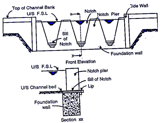
4. Trapezoidal Notch Fall:
It was introduced in 1894, by Reid. It consists of a number of trapezoidal notches, in a higher breast wall, across the channel, with a smooth entrance and a flat circular lip projecting downstream from each notch to disperse water
In the fall, the notches were designed to maintain the normal depth of flow in the upstream channel at any two discharge values, the variation at intermediate values being small.
So, the depth-discharge relationship of the channel remained almost undisturbed by the introduction of the fall. These types of falls were very popular in India, however, after few types of falls were introduced the trapezoidal notch falls were become obsolete.
5. Vertical Drop Type Falls:
In this, the clear nape leaving the crest is made to impinge into cistern below. The cistern provides a water cushion and it helps to dissipate the surplus energy of falling jet.
In the earlier types of vertical drop type falls, the dimensions of the cistern were decided, arbitrarily, on the basis of the past experience of the designers.
Then a grid consisting of bulks of timber spaced few centimeters apart, was provided in the cistern to intercept the falling naps and thus dissipate its surplus energy.
Because of the need of frequent of replacement of the timber grid, this type of falls was abandoned. This type of fall was used in Sharda canal project in Utter Pradesh, it is running very smoothly.
6. Glacis Type Fall
In this type, the hydraulic jump or the standard wave is being for the dissipation of energy.
Before the introduction of this type of fall in Punjab a flumed fall with straight glacis was introduced, but some serious problems were the functioning that type of fall. One of the serious problems, was that, even after the formation of the hydraulic jump, there was still a considerable extra energy in water.
Another problem was due to too rapid expansion after the fluming eddies were developed, causing deep scours. So, a lot of researches were carried to eliminate these faults and finally two new types of falls, namely Montague and Inglis were developed.
In Montague type of fall, the straight glacis has been replaced by Parabolic glacis community, known as Montague profile.
In Inglis type fall straight glacis is provided but at a certain distance from the toe of the glacis, a baffle wall of certain height is provided both of these types at all are designed to hold the hydraulic jump stable, to affect the maximum dissipation of energy.
7. Meter or Non-Meter Fall:
One that can measure the discharge is called as Meter fall, and another that cannot measure the discharge of the channel is called as Non-Meter fall
Key takeaways:
1. Gravity dam:
A structure which is designed to resist the external forces by its own weight is called as gravity dam.
Design of such dam is done in such way that its own weight resists the external force. Gravity dam structure is more rigid and most durable and requires less maintenance.
Gravity dam may be constructed of masonry or concrete. Hence concrete dam is a gravity dam. Concrete gravity dam is more preferred these days and mostly constructed.
Site selection for such dam is prime importance and site for dam should be selected in such way that, there exists a natural foundation strong enough to take the huge amount of weight of the dam.
Gravity dam is generally straight in plan and in case of special cases, it may be slightly curve.
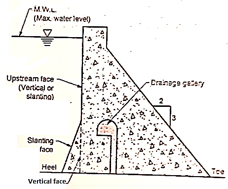
2. Typical cross section
For any suitable conditions, gravity dam may be constructed to greater heights. Grande Dixence dam in Switzerland is highest concrete gravity dam and its height is 284 m and highest concrete gravity dam in India is a Bhakra dam with a height of 226 m.
In such structure, the ratio of base width to height is less than 1.1.
Fig. shows a typical cross-section of concrete dam (Gravity).
To release the uplift pressure, a drainage gallery is provided with respect to base of the dam as shown in Fig.
The upstream face of concrete dam may be vertical throughout the height of a dam or partly kept slanting for some of its length as shown in Fig. uplift pressure is caused by the seeping water.
3. Various forces acting on gravity dam
1. Water pressure (P)
2. Silt pressure
3. Uplift pressure
4. Wave pressure
5. Ice pressure
6. Weight of the dam
7. Earthquake forces or seismic forces
1. Water pressure (P):
In concrete gravity dam, the water pressure is more major and important external force.
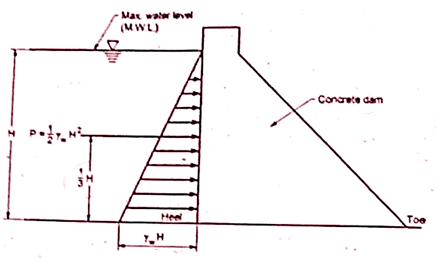
The weight of the water stored on the upstream side on the dam exerts the horizontal water pressure and it can be estimated from the rule of hydrostatic pressure distribution. Hydrostatic pressure variation or distribution is triangular in shape as shown in Fig.
For vertical upstream face of dam, the intensity of water pressure at the water surface is zero and at the base, it is equal to 
Water pressure at water surface = 0
Water pressure at the base =
P = Resultant force caused by external water pressure acting at H from base = H²
1/3 H from base = =
Where,
 = unit weight of water = 9.81 kN/m
H = depth of water
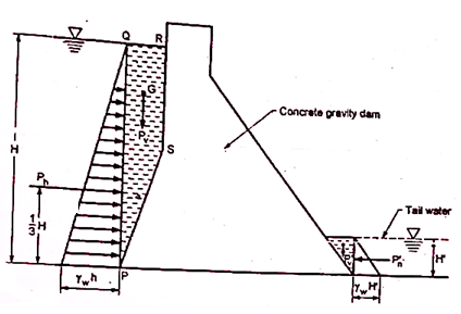
For upstream face partly vertical and partly with slope as shown in Fig. then resultant water force (P) is resolved into the components as
(i) Horizontal component (P) = = acting at H from the base
(ii) Vertical component (P) = weight of the water stored in column PQRS and acts at the centre of gravity of area. Note that if there is tail water on the d/s side of dam as shown in Fig. then resultant force on downstream face of tail water has also the components as s(P) = Y, H² acts at f Horizontal components (P) = Ha H from base
2. Silt pressure
Silts are get deposited against the upstream face of the dam. Force exerted by silts with external water pressure can be expressed by Rankine's formula as follows:
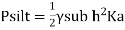 and this silt force acts at from base
Where,
P=Silt force or force exerted by silt.
 = Submerged unit weight of silt material
h = height of silt deposited
ka, = Coefficient of active earth pressure of silt
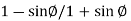
Where,
Angle of internal friction of soil and cohesion is neglected.
For upstream inclined face, the vertical weight of the silt supported on the slope also acts as a vertical force. If any data of silt is not available or reliable, then U.S.B.R. recommendation can be taken into consideration in which deposited silt can be taken as equivalent to a fluid exerting a force with a unit weight equal to 3.6 kN/m' horizontally and with a unit weight of 9.2 kN/ m vertically.
Therefore, the total horizontal force = 3.6 9.246 and total vertical force 9.2 1.8 h kN/m run 4.6 h kN/m run.
3. Uplift pressure
Seepage of water is occurred through cracks, fissures and pores of foundation material and also through dam body. This water is then come to bottom through the joints between the dam body and its foundation at the base,
This seeping water finally exert an uplift pressure on the base of the dam. Hence uplift pressure is major external force and has to be considered in the design of dam.
Uplift pressure reduces the downward weight of the body of the dam and ultimately affects the dam stability.
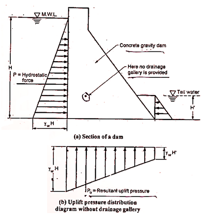
According to the recommendation of United States Bureau of Reclamation (U.S.B.R.), the uplift pressure intensities at the heel and at the toe is equal to their respective hydrostatic pressures and shown by straight lines in between as shown in Fig
Fig. shows uplift pressure diagram Le. U diagram when drainage gallery is not provided.
Fig. shows uplift pressure diagram when drainage gallery is provided. In this case, it is recommended that the uplift pressure at the base of the drainage gallery is equal to the addition hydrostatic pressure at the toe and one third difference of the hydrostatic pressures at the heel and toe.
Uplift pressure =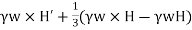
Note that it is considered or assumed that earthquake forces do not affect the uplift pressure.
Remedial measures
Uplift pressure can be controlled by constructing the following three things:
1. Cut-off walls under upstream side
2. Drainage channels between dam and its foundation
3. Pressure grouting to the foundation.
4. Wave pressure
When the wind blows; the waves are produced on the surface of stored water in the reservoir. These waves produce wave pressure towards the downstream side.
Wave pressure developed on the surface of reservoir depends upon the wave height.
Let h = wave height
... for F32 km
 ...for F> 32 km
F= Fetch or straight length of water expanse in km
V Wind velocity in km/hr.
Let. P maximum pressure intensity caused by wave action acting at meters above the still water surface
The pressure distribution due to wave action can be assumed as triangular with a height of has shown in Fig.
Where,
Pw=2.4 
P = Total wave force = 
P = 19.62 h kN/m Total force (P) caused by wave action 3 h above water surface of reservoir.
5. Ice pressure
In cold region of countries, ice is formed on the surface of the reservoir, which further can expand or meet. Hence the dam face should able to resist the force exerted by the melting ice which has magnitudes varies from 250 kN/m² to 1500 kN/m² depending upon the atmospheric temperature.
For the sake of design, the average value like 500 kN/m² can be allowed and considered under the ordinary conditions of the dam
The weight of the dam and its foundation has prime importance because they are major resisting force. A unit length of the dam is taken in two dimensional (2-D) analyses
The overall cross section of dam is split up into triangles and rectangles of which, weight with their centre of gravity is determined.
Then resultant of all downward forces gives the total weight of the dam which acts through centre of gravity of the dam.
6. Earthquake forces or seismic forces
In the earthquake prone area, if the dam is to be constructed, then earthquake impact should be considered.
The effect of an earthquake is equivalent to give acceleration to the foundation of the dam in the direction in which the waves travel at the moment.
Earthquake waves can be moved in any direction’s sake of design the earthquake wave force should be resolved horizontally and vertically or resolved into horizontal and vertical components.
Therefore, the accelerations developed by an earthquake has to be taken account.
Let a, = horizontal acceleration and a = vertical acceleration
The value of accelerations are generally expressed in percentage of activation because of gravity (g) and they are considered as a = 0.1g or a = 0.2 g.
For high dam in earthquake zone, the average value of a taken from 0.1 g to 0.15 g and the area which is not subjected to extreme seismic, the value a, = 0.1g and a, = 0.05 g is taken in design. The area which is not subjected to earthquakes, the value of acceleration is neglected.
4. Combination of forces for design
The structural integrity of a dam has to be maintained across the range of circumstances or events likely to arise in service. The design is therefore determined through consideration of corresponding spectrum of loading conditions. In all foreseeable circumstances the stability of the dam and basis have to be ensured, with stresses contained at desirable ranges and watertight integrity basically unimpaired. The Gravity dam is subjected to the subsequent principal forces
1. Water Pressure (Water load)
2. Weight of the Dam (Self weight)
3. Seepage and Uplift Pressure
4. Wave Pressure
5. Silt Pressure
6. Ice Pressure
7. Wind Pressure
8. Earth Quake Force
5. Modes of failure and criteria for structural stability
A gravity dam can fail because of the subsequent reasons:
If the ensuing of all of the viable forces (inner in addition to external) performing at the dam cuts the bottom of the dam downstream of the Toe, the darn might overturn until it may face up to tensile stresses. To shield the dam in opposition to overturning, the ensuing of the forces need to in no way be allowed to move down flow of the Toe.
If resultant is maintained within side the frame of the dam, there could be no overturning. All the forces performing at the dam purpose moments. Some of the forces assist keep balance of the dam, whilst others try and disturb the steadiness. The moments of the forces, assisting dam to keep its balance are realize resisting moments (Mr).
The moments of the forces that try and disturb the steadiness of the dam are called overturning moments (Mo). As quickly as Mo exceeds Mr overturn of the dam might take place. Factor of safety (F.S.) in opposition to overturning may be located out as follows. F. S=Resisting−moment Overturning−moment =M0 Mr
The price of F.S. in opposition to overturning need to now no longer be much less than 1.5.
2. Sliding of the Dam.
In this mode of failure, the dam fails in sliding. The dam as an entire slide over its basis or one a part of the dam might also additionally slide over a part of the dam itself, mendacity beneath it.
This failure takes place while the horizontal forces inflicting sliding are extra than the resistance to be had to it, at that level.
The resistance towards sliding can be because of friction on my own or it could be because of a mixture of friction and shear energy of the joint. Shear energy develops at the bottom if benched basis is provided.
At different joints the shear energy is advanced through laying joints cautiously so one can achieve true bond. Interlocking of stone blocks in stone masonry additionally facilitates growth shear energy.
In case of low masonry dams shear energy isn't always taken into account. In that case aspect of protection towards sliding is acquired through dividing internet vertical forces through internet horizontal forces and multiplying the consequent through coefficient of friction μ.
3. Crushing or Compression Failure.
If the compressive strain evolved everywhere within side the dam exceeds the secure permissible limit, the dam can also additionally fail via way of means of crushing of the dam itself or of foundation.
The most compressive strain can broaden at toe while reservoir is complete of water.
If reservoir is empty the most compressive strain is possibly to broaden on the heal of the dam.
The importance of most compressive and minimal compressive stresses may be determined out via way of means of the usage of following equation.
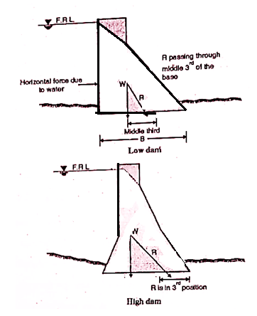
6. High and low gravity dams
A gravity dam is said to be low when its height in m is less than w (1+S)
Where A = Safe compressive stress allowable for masonry or concrete of dam.
V = Special weight of water
S = Specific gravity of dam material
In low dam resultant passes through lower middle third point.
A gravity dam is said to be high dam when its height is more than W (1+S) meters
In high dam maximum permissible compressive stress would be exceeded if the resultant were pass through the middle third point to keep maximum compressive stresses in middle third downstream slopes are made flatter and upstream slope is also given slope of about i in 10 and lower portion.
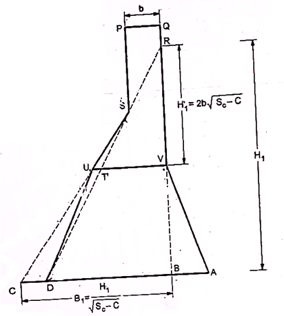
7. Typical section of low gravity dam
After designing of the top width and free board the economical section of low gravity dam can be drawn in Fig.
The base width (B₁) of the triangle RCB can be determined from the following equation as:

μ = frictional resistance or by
By taking three four trials, the height H as shown in Fig. can be determined and the approximate first value of H, can be chosen by the equation as:
H = 2b √Sc-C
Hence from R to V as shown in Fig the upstream face can be kept vertical up equal to height H.
Below height H as shown in Fig. the upstream face and downstream face are made to slop in such way that tension is not developed anywhere in the dam and the resultant force remain as close to the outer third point for full reservoir whereas resultant force remains close to the inner third point for empty reservoir it is termed as h 3h gravity dam.
Key takeaways:
1. Earth Dams:
The dams which are constructed of earthen materials such as gravel sand, silt and clay are called earthen dam
It has trapezoidal section with a top width of 3 to 10 m and upstream slope of 1 V: (2.5 to 4) H downstream slopes (V:2 to 3) H
2. Types:
The various types of earthen dam are as follows,
2. Types of earth dam based on methods of construction
There are mainly three types of earthen dams:
Types of earth dams based on methods of construction are as follows:
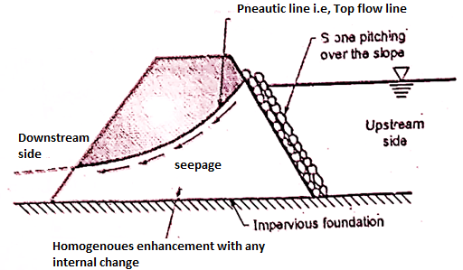
1. Homogeneous embankment type of dam
It is one of the types of earthen dam which consist of earthen embankment of simple type and made in a single material hence it is homogeneous throughout.
Fig shows homogeneous type embankment dam without any internal drainage system.
When only one type of material is locally available and which is economical, then a purely homogeneous section is used.
This type of homogeneous section is used for low to moderately high dams and also for levees.
A rely homogeneous section creates great problem of seepage and section has to make a big section or a huge section so as to make the whole structure more safe against piping, stability c
Hence due to fact of piping and stability, a homogeneous section is built-up with an internal drainage system like a horizontal drainage filter as shown in Fig. 6.1.2; rock toe etc.
Internal drainage system keeps the top seepage line (phreatic line) properly within the body of the dam. Hence internal drainage system is more useful and always provided nearly all types of embankments.
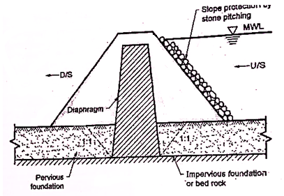
2. Diaphragm type of embankment dam
This type of embankment dam consists of an impervious core called as diaphragm which is surrounded by earth or rock fill.
Impervious core or diaphragm is made of impervious soils, timber, concrete, steel or any other suitable material. Diaphragm serves as a obstacles or water barrier so as to avoid the seepage through the dam.
Diaphragm is located at the centre of the dam section or located or placed at the upstream face as a blanket. Diaphragm should be well connected to the bed rock or to a very impervious 'foundation material. Due to this connection between diaphragm and bed rock or impervious foundation, the possible excessive under seepage through the existing pervious foundation can be prevented.
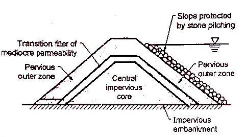
3. Zoned type embankment dam:
This type of embankment consists of usually a central impervious core covered by a transition zone which is surrounded by a pervious outer zone.
Fig. shows the zoned embankment type of dam.
Central core is useful to check the seepage. The transition zone is advantageous for preventing the piping through cracks which may likely to set up in the central core.
The outer zone provides stability to the central impervious fill and also distributes the load over the larger area of foundations.
Clay is highly impervious, but sometimes it does not make the best core, if it expands and shrinks in large extent. Hence clay is sometimes mixed with fine gravel or fine sand so as to make the most suitable material for the central core sometimes silt clay or silts can be used as the central core materials.
In outer shell, the coarse sand and gravels which acts as a freely draining material are used.
In between, inner zone and outer zone, the transition filters are provided. When there is an abrupt change of permeability from one zone to another zone, then in such circumstances, transition filters are best suited and hence provided.
3. Causes of failure
The following are the points due to which earthen dam may fail.
1. Improper construction methods and techniques.
2. Improper maintenance.
3. Improper design due to insufficient in investigation.
4. Preliminary section
An earthen embankment is a raised confining shape crafted from compacted soil. The reason of an earthen embankment is to restrict and divert the typhoon water runoff. It also can be used for growing infiltration, detention and retention facilities. Earthen embankments are usually trapezoidal in form and maximum easy and monetary in nature.
They are especially constructed with clay, sand and gravel, for this reason they may be additionally called earth fill dams or earthen dams. They are built wherein the inspiration or the underlying fabric or rocks are susceptible to guide the masonry dam or wherein the best able rocks are at extra depth. They are enormously smaller in top and broader on the base.
Components of An Earthen Dam
The diverse additives of an earthen dam are proven in
Shell, Upstream Fill, Downstream Fill or Shoulder: These additives of the earthen dam are built with pervious or semi-pervious substances upstream or downstream of the core. The upstream fill is known as the upstream shell and the downstream component is the downstream shell.
Upstream Blanket: It is a layer of impervious fabric laid at the upstream facet of an earthen dam wherein the substratum is pervious, to lessen seepage and growth the route of glide. The blanket decreases each the seepage glide and extra strain at the downstream facet of the dam. An herbal blanket is a cowl of obviously taking place soil fabric of low permeability.
Drainage Filter: It is a blanket of pervious fabric built at the inspiration to the downstream facet of an earthen dam, to allow the release of seepage and limit the opportunity of piping failure.
Cutoff Wall or Cutoff: It is a wall, collar or different shape meant to lessen percolation of water via porous strata. It is furnished in or at the foundations.
Riprap: Broken stones or rock portions are positioned at the slopes of embankment mainly the upstream facet for protective the slope in opposition to the motion of water, especially wave motion and erosion.
Core Wall, Membrane or Core: It is a centrally furnished pretty impervious wall within side the dam. Its assessments the glide of water via the dam section. It can be of compacted puddle clay, masonry, or concrete constructed within side the dam.
5. Seepage control
The seepage through embankment is by various methods:
Various Methods of Control of Seepage through Embankment
1. Provision of impervious core
2. Provision of rock too
3. Horizontal drainage blanket
4. Relief well
5. Chimney Drain
1. Provision of impervious core
For reducing seepage through body of dam a core of impervious material such as silts clay or clayey silt is provided which forms barrier within the body of dam against seepage water it is selected depending upon availability of materials topography and site etc.
2. Provision of rock toe
It also helps in reducing seepage as it changes path of seepage line and prevent sloughing of the downstream toe.
3. Horizontal drainage blanket
The seepage can be controlled by providing horizontal drainage blanket along with rock toe.
4. Relief wall
The main purpose of relief well is to decrease the sub-stratum uplift pressure downstream of the dam. If the relief well is not provided, there will be formation of sand boils and possibly sub-surface piping.
Relief wells intercept the seepage and control the outlet for seepage. They type of seepage control system was first used by U.S. corporation of Engineers.
5. Chimney Drain
The horizontal permeability is more than vertical for high degree of embankment stratification and it causes the greater horizontal spread of seepage.
To control this seepage, a vertical drain called as chimney drain is provided which can completely intercept the embankment seepage.
Seepage Control through the Foundations
Seepage through the foundations can be controlled by providing the following elements:
Key takeaways:
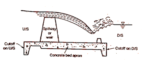
It is an arrangement provided at the crest of dam to expel the excess water rises above the full reservoir level.
This is ne essay otherwise water will go on rising even above HFL and will start flowing from top of dam which may affect stability of dam.
Therefore, it is very essential to provides spillway to dispose surplus water on downstream side.
The component part of spillway is:
1. Body or spillway
2. Approach channel
3. Guide wall.
4. Energy dissipaters
5. Tail channel
The passage provided for disposal of surplus flood water on the downstream side without affecting stability of dam is called as spillways.
Sometimes gates are provided to control flow over the spillway crest.
Classification of Spillways Based on Operation
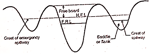
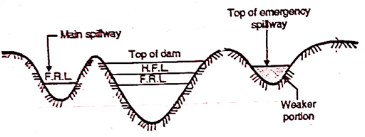
It is provided with an earthen dam. In such spillway part of the length of earthen dam is kept weak above FTL/FRL (Full tank/Reservoir level).
When abnormal high intensity flood occurs, the weaker portion gets washed and flood water flows through that portion which acts as additional spillway and thus avoids possibility of failure of the dam.
The various conditions which may lead to emergency are:
1. When there is mal functioning of spillway gate.
2. When actual flood exceeds the design flood etc.
2. Service Spillways
The service spillways are masonry or concrete structure provided with necessary component.
It is necessary for all dams and in most dam, it is the only spillway designed to pass design flood.
3. Auxiliary spillways
This type of spillway is provided so as to supplement the main spillway. It operates only when the design floods in the main spillway is more or exceed.
Classification of Spillway Based on Gates
Spillway are classified into various types based on gates as follows:
1. Gated spillway
2. Ungated spillway or uncontrolled spillway
1. Gated spillway
Gates are provided over the crest of spillway. It stores more water and efficiently and effectively controls the outflow from upstream and downstream side
2. Ungated spillway or uncontrolled spillway
In such type, no gates are provided over the crest to control the flow and hence it does not need any operation of gate. Surplus flow of water cannot be controlled by un gated spillway.
Classification of Spillway Based on Features
1. Ogee Spillway
2. Bar Spillway
3. Straight drop spillway or free over fall spillway
4. Side channel spillway
5. Chute or open channel or trough spillway
6. Shaft spillway or morning glory spillway
7. Siphon spillway
(a) Saddle siphon spillway
(b) Volute siphon spillway
8. Tunnel spillway
9. Stopped spillway
10. Saddle spillway
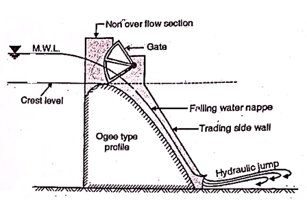
1. Ogee Spillway:
The shape of spillway is ogee or S shaped. The main difference between free over fall spillway and ogee spillway is that in case of free over fall spillway water flowing over the crest of spillway drops vertically as free set where in ogee shaped spillway water is guided smoothly over the crest and is made to guide over the downstream face of the spillway.
It is ideal spillway as water flowing over the crest of spillway always remains in contact with the surface spillway.
2. Bar Spillway
It consists of rectangular masonry concrete bar with crest width1 to 1.5 m.
It is low height spillway, founded on concrete block, rest on hard rock foundation sometime precast concrete blocks are used for coping of the crest.
The top of crest is at FRL.
3. Vertical drop spillway
The spillways in which the flow drops freely from the crest is called straight drop.
Three provisions or Methods to avoid erosion on the d/s side
4. Side channel spillway
When it is not possible to use over fall spillway especially in embankment dams, then side channel spillway is more suitable. In such type of spillway, water flow after passing over the crest is further conveyed in the side channel which running parallel to the crest as shown in Fig.
This type of channel is preferred under following situations:
(i) It is adopted in case of a long overflow crest provided to limit the surcharge head.
(ii) It is adopted or preferred when the control structure is to be joined to a narrow discharge channel.
(iii) It is preferred when the abutments are very steep
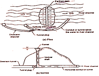
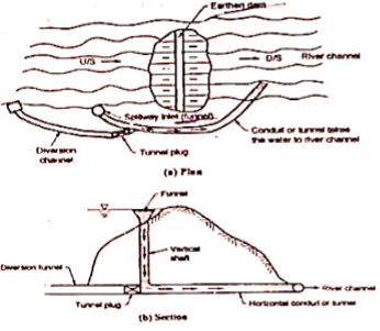
5. Shaft spillway or morning glory spillway
This type of spillway consists of a vertical flaring funnel act as the crest of the spillway and its bottom end connected to the shaft either vertical or inclined which is further connected at its lower and to a horizontal tunnel extending through or around the dam as shown in Fig. The water flow passes though tunnel is taken to the downstream river channel.
Key takeaways:
References:


