Unit - 4
Rolling loads and influence lines for determinate structures
1. Influence line:
An influence line for a given characteristic, which includes a reaction, axial pressure, shear pressure, or bending moment, is a graph that indicates the version of that characteristic at any given factor on a shape because of the software of a unit load at any factor on the shape. Influence line is additive and scalar. The scaled most and minimal are the essential magnitudes that need to be designed for within side the beam or truss.

Examples:
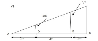
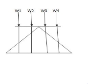
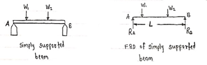
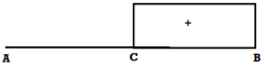
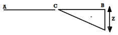
1] A simply supported beam is subjected to loads as shown in fig.
Using influence lines find
support reactions
shear force & bending moment at ‘C’
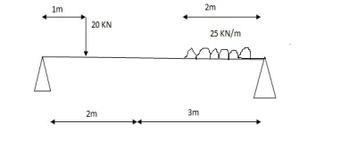
Solution:
1) VA& VB
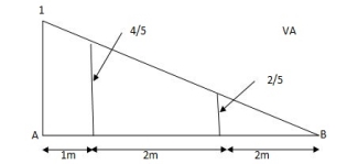
VA = 20 + 25 1 = 16 + 10 = 26 KN
VB = 20 + 25 + = 4 + 40 = 44 KN
= =0.6
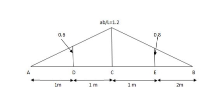
SF@ c = 20 (-0.2) + 25= 5KN
BM@ c = 20 (0.6) + (2 0.8) (25)
= 32 KN. M
2. Rolling loads:
Loads which roll over the given structural detail from one quit to the every other quit. In a rolling load most shears force, bending moments.
Example: train on the railway track, automobiles at the bridges or roads are rolling loads etc.
Rolling loads there are 3 types:
1. Single factor rolling load
2. Uniformly distributed load
3. Two factor rolling load
Uniformly distributed load there are main types: 1) Longer than span 2) Smaller than span
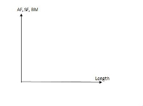
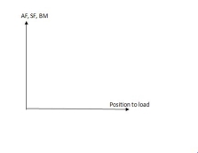
ILD for beams and rolling load:
It is a diagram which shows version of AF, SF and BM on the sort of characteristic at a unique section for numerous functions of moving load.
It is a diagram which indicates variation of AF, SF and BM on any such function at a particular section for various position of moving load.
AFD, SFD, BMD ILD
Load position fixed (for particular %)
How to find value of function from ILD
i) Structure subjected to point loads
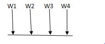
Meg. of function = W1Y1 +W2Y2 +W3Y3+W4Y4
ii) Structure subjected to udl
Magnitude of function = {Area of ILD under UDL} 𝓌
i)VA =? (ii) MA=? (iii) SF = (iv) BM =
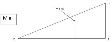
1) ILD’s for VA & MA
Consider unit load at a distance
MA = MA -1 (x) =0
MA =x
X VA MA
0 1 0
L 1 0

ILD for bending moment at A is as below

ILD for shear force & BM at ‘C’
SF@ c =0, BMC =0
SFC =1; BMC = -1 (x-a)
For x = a; BM@ c =0 X = L;
BMC = -1(1-a) c b
2)
1) ILD’s for VA& VB
x VA VB
0 1 0
L 0 1
2) SF c & BM c
1)
2)
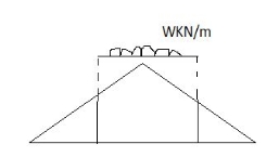
Example:
1] A simply supported beam subjected to moving udl

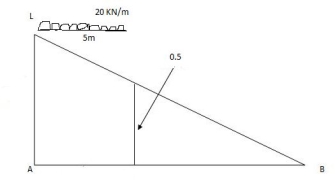
Solution:
VA max = (20) = 75 KN
VA max = 20 = 75 KN
Note:-
Absolute maximum shear force is nothing but greater 07 VA, max & VB, max
Abs. max SF = 75 KN
2)
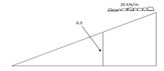
Max.(–ve) SFc = (-) (20)
= ( ) 16KN
Max. +ve SF c =
=35KN
Max. SFc = 35 KN
Note:
When length of udl is smaller than bas of triangle, placed udl such that load per a on LH & RHS of height of triangle is same.
= x = 2m
= (5) (20) =180 KNm
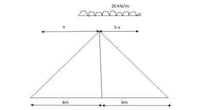
Abs. max BM = (5) (20) =187.5 KNm
Diagonal members design
Top camp
Key takeaways
1. Find VA VB
2. Find SF
2. Find BM
3. Draw influence line
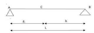
Simply supported beam –
A beam which is just resting on the supports at the end without any connection is known as simply supported beam. It is generally used for vertical landing system.
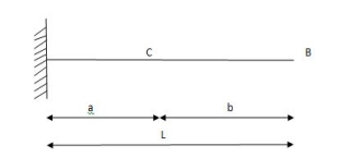
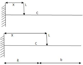
4.3 Cantilever
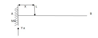
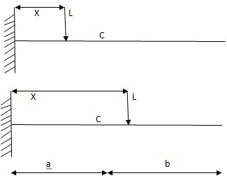
Consider a cantilever beam of span L to unit load at a distance X from free end.
The influence line diagram for reaction at support shear force and bending moment at fixed end and at any section are to be determined.
Diagram:
i) ILD for reaction at A to RA =1
Diagram:

ii) ILD for S.F at A
S.F at A = 1 (constant)
Hence, ILD for S.F. A is as shown in fig.
Diagram:
iii) ILD for B.M at A
MA = -(L-x) Linear variation
When x= 0, MA= -L
When x= L, MA= 0
This ILD for B.M. at A
Diagram:
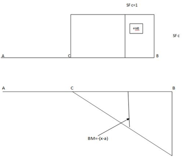
iv) ILD for S.F at C
When x < a; S.F at C = 1 constant
When x > a; S.F at C = 0
ILD for SF at C
Diagram:
v) ILD for B.M at C
For X < a B.M at C = -1(x-a) Linear variation
When x = 0 B.M.@c = -a
When x = a. B.M.@c = 0
For x > a M at C = 0 constant
Hence ILD for B.M at C as shown in fig.
Diagram:
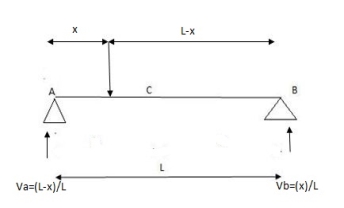
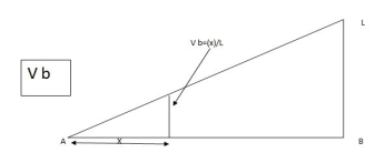
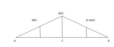
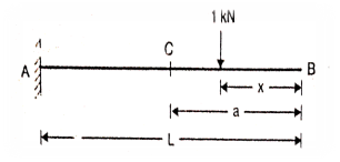
Consider a simply supported beam AB as shown in fig. Let a unit load moves from left end A to the right end of B
At any instant the unit load at a distance X from C
RA = (L-x)/L
RB = X/L
1. ILD for RB:
When unit load at A, x = 0
RB = X/L = 0/L = 0
Diagram
When unit load is at B, x = L
RB = x / L = 1/1= 1
Therefore, ILD of RB is a triangle varying from zero ordinate at A and one at B
2. ILD for RA:
When unit load at A, x = 0
RA = (L-x)/L = 1
When unit load is at B, x = L
RA = (L-x)/L = 0
Therefore, ILD of RA is a triangle varying from one coordinate at A and zero at B.
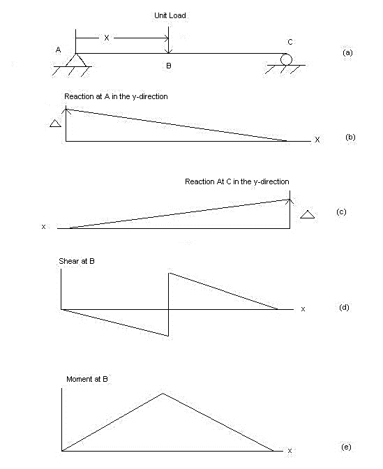
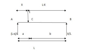
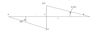
1. ILD for shear force at a section
Consider a unit load is moving along the span of a simply supported beam girder AB
Let C be the section for which ILD for shear force has to be draw.
a. When unit load is between A to C the S.F at C is - RB therefore, the part of ILD for RB is applicable.
i.e. between A to C
b. When unit load is between C to B, then shear force at C is +RA Therefore, a part of ILD for RA is applicable
i.e. between C to B
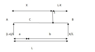
2. ILD for the B.M at a section
Consider a beam AB is simply supported at the end.
Let C be the point or section for which we have to draw ILD for B.M
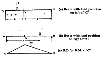
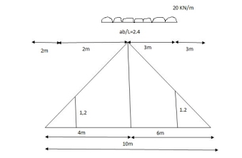
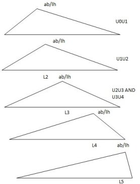
a. When unit load is at a distance x from A i.e. in between A to C. The moment at C is given by
Mc = RB x b
Since, RB = x/L
Mc = (x/L) x b
This equation is applicable for the portion AC for any position of unit load
At x= 0 Mc = 0
At x = a. Mc = ab/L
Therefore, the B.M varies from zero to A to ab/L at C
b. When unit load at a distance x from A i.e. in between C to B then,
Mc= RA x a
Since, RA = (L-x/L)
RA = (L-x)/ L X a
This equation is applicable for any position of unit load in portion CB
At x = a. Mc = (L-a/L) x a = ba/L
At x = L. Mc = 0
Therefore, BM diagram varies from ab/L at C to zero at B.
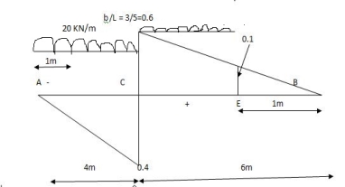
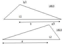
Example:
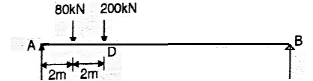
Two-wheel loads 80 KN and 200 KN, spaced 2 m apart move on a girder of span 16 m. Find the maximum positive and negative shear force at a section 4 m. from the left end. Any wheel load can lead the other.
Solution:
1. First draw the ILD and SF at D

2. Maximum positive SF at D
Place 200 KN load just on the right side of D. i.e. at D and other load should be placed at 2 m on the right side of D.
Maximum positive SF at D = 200 x (3/4) + 80 x (5/4) = +200KN
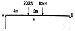
3. Maximum negative SF at D
Place 200 KN load just on the left side of D i.e at D and the other load should be placed at 2 m on the left side of D
Maximum negative SF at D= -(200 X (1/4) + 8 X (1/8) ) = -60 KN
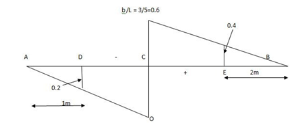
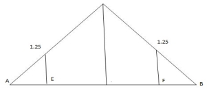
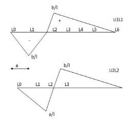
1. Point loads
Example:
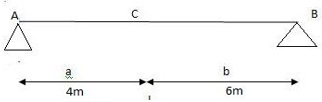
For the simply supported loaded as shown in fig. Draw (1) ILD for RA (2) ILD for RB. Determine the magnitude of RA and RB

Solution:
1. ILD for RA
Join 1 and 0 by straight line and the resulting diagram will be
ILD for RA
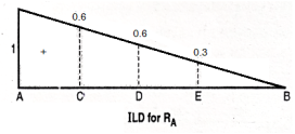
Originate at E = 1/10 X 3 = 0.3
At D = 0.6 and at C = 0.8
2. ILD for RB
Join 0 and 1 by straight line and the resulting diagram will be ILD for RB
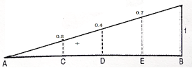
Originate at C = 1/10 X 2 = 0.2
At D = 0.4
At E = 0.7
3. Magnitude of RA and RB
RA = magnitude of load X corresponding ordinates on ILD
RA = 100 X 0.8 + 50 X 0.60 + 200 X 0.3
RA = 170 KN
Similarly
RB = 100 X 2 + 50 X 0.4 + 200 X 0.70
RB = 180 KN
2. Udl
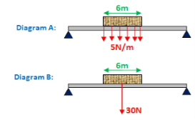
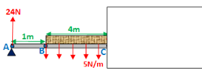
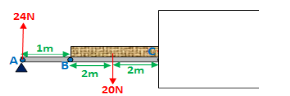
A brick lying on a beam is located below. The weight of the brick is distributed evenly on the beam (shown in diagram A). The brick has a brick weight of 5N per brick meter (5N/m). Since the brick is six meters long, the brick's total weight is 30N. In diagram B, this is shown. A simplification of diagram A is diagram B. You will need to be able to convert a type A diagram to a type B diagram, as you will see.
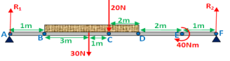
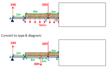
At point C, I have added an external force and a point moment to the diagram below to make your life harder. This is the most difficult kind of question I can think of, and step by step I'm going to do the shear force and bending moment diagram for it.

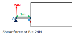
Firstly, identify the key points at which you will work out the shear force and bending moment at. These will be points: A, B, C, D, E and F.
When you work out the bending moment and shear force at any given point, as you would have noticed, sometimes you just work it out at the point, and sometimes you work it out just before and after. Here is a summary: If you are dealing with a point force (points A, C and F in the diagram above), work out the shear force before and after the point when drawing a shear force diagram. Otherwise (for points B and D), just work it out at that point. If you are dealing with a point moment (point E), work out the bending moment before and after the point moment, when drawing a bending moment diagram.
You want to work out the values of R1 and R2 after identifying the key points. Now, as shown below, you need to convert it to a type B diagram. Notice that between points B and D, the 30N force acts right in the middle.
Force equilibrium: R1 + R2 = 50
Take moments about A:
4·30 + 5·20 + 40 - 10·R2 = 0
R1 = 24N, R2= 26N
Update original diagram:
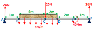
Shear force diagram
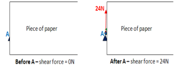
Point A:
Point B:
Notice that there is no effect on point B of the uniformly distributed load.
Item C:
Right before C:
Now convert to a type B diagram. Total weight of brick from point B to C = 5x4 = 20N
Shear force before C: 24 - 20 = 4N

Shear force after C: 24 - 20 - 20 = -16N
Point D:
Shear force at D: 24 - 30 - 20 = -26N
Point F:
(I have already converted to a type B diagram, below)

Finally plot all the points on the shear force diagram and join them up:

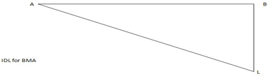
The second or moment envelope curve defines the intense boundary values of bending second alongside the beam because of essential placements of layout stay loading.
Note that no person second diagram defines the top or decrease certain throughout the whole 3 spans. It has been essential to do all six analysis.
Figure indicates simply the top and decrease bounds for second alongside the beam.

This is a second envelope diagram. Note that the instant at the beam will always be among the top and decrease bounds. These are the crucial values wanted for design.
Similar methods are taken the increase envelopes for different load outcomes including shear or deflection.
The fundamental steps are the same:
Identify the important load instances the usage of have an effect on lines.
Analyze every of the burden instances
For every place alongside the member, decide the higher and decrease sure values and graph them.
By a few astute commentary it's miles feasible to provide you with different methods to the problem. One such technique is offered withinside the subsequent section.
Key takeaway:
1. Identify the important load instances the usage of have an effect on lines.
2. Analyze every of the burden instances
3. For every place alongside the member, decide the higher and decrease sure values and graph them.
References:
1. Theory and Problems in Structural Analysis by L Negi, Mc Graw Hill
2. Structural Analysis by T.S. Thandamoorthy, Oxford University Press
3. Basic Structural Analysis by C S Reddy, McGraw Hill
4. Elementary Structural Analysis by Norris and Wilber, McGraw Hill
5. Structural Analysis by Aslam Kassimali, Cengage Learin
6. Analysis by R.C. Hibbeler, Pearson Education


