Unit 4
Heat Exchangers
2. Classification of heat exchangers
Heat exchanger are classified based on
2.1 Heat exchangers according to flow arrangements
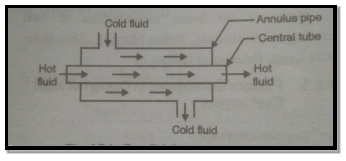
Fig4.1 Parallel flow heat exchanger
II. Counter flow heat exchanger:
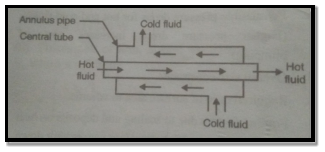
Fig4.2 Counter flow heat exchanger
III. Crossed flow heat exchanger:
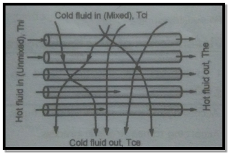
Fig4.3 Crossed flow heat exchanger
2.2. Heat exchangers according to heat transfer process
Fig4.4 Direct contact type heat exchangers
II. Transfer type heat exchanger:
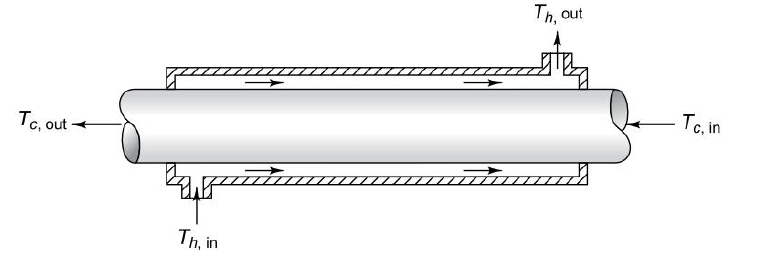
Fig4.4 Transfer type heat exchanger
III. Storage type heat exchanger:
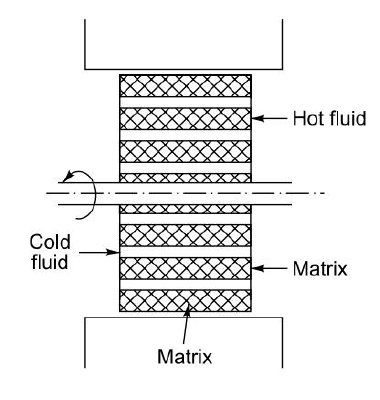
Fig4.6 Storage type heat exchanger
2.3. Heat exchangers according to geometry
II. Shell and tube type heat exchanger:
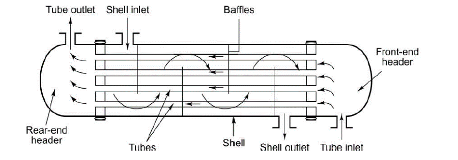
Fig4.7 Shell and tube type heat exchanger
III. Finned tube type heat exchanger:
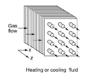
Fig4.8 Finned tube type heat exchanger
3. Temperature distribution in heat exchanger
Heat transfer takes place from hot to cold fluid in heat exchangers. The temperature of this liquid can be expressed as graphs as follows
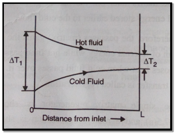
Fig4.9 Parallel flow heat exchanger
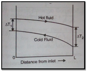
Fig4.10 Counter flow heat exchanger
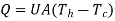
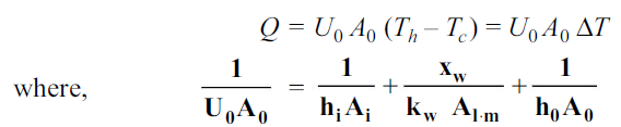
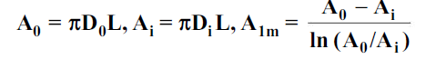
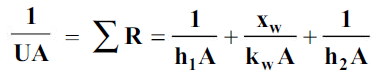
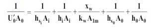
4. Overall heat transfer coefficient and Fouling factor
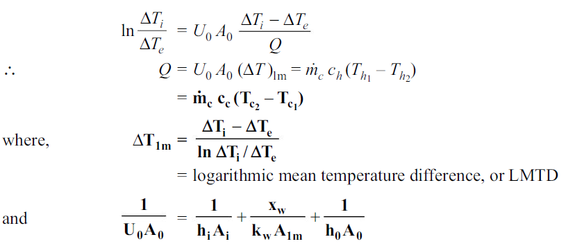
If Th and Tc represent the bulk mean temperatures of the two fluids on either side of the plane wall, then
Where

xw being the thickness of the wall, kw the thermal conductivity and h1 and h2 the heat transfer coefficients on the two sides.
As all the heat exchangers consist of tubes which are cylindrical in shape, for heat transfer through cylindrical wall
…(4.1)
Equation (4.1) holds for clean surfaces on both sides of the cylindrical wall.During normal heat exchanger operation, surfaces are often subject to fouling by fluid impurities, rust formation, or other reactions between the fluid and the wall material. The subsequent deposition of a film or scale on the surface can greatly increase the resistance to heat transfer between the fluids. So that,
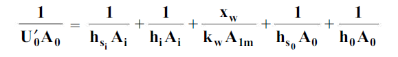
…(4.2)
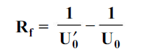
where hsi and hs0 are the scale heat transfer coefficients and Uo’ is the overall heat transfer coefficient with scaled surfaces. The reciprocal of the scale heat transfer coefficient is called the fouling factor Rf. Fouling factors which reduce the performance of heat exchangers can be determined experimentally
…(4.3)
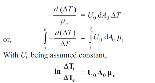
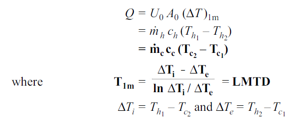
5. Log Mean Temperature Difference
Parallel flow heat exchanger
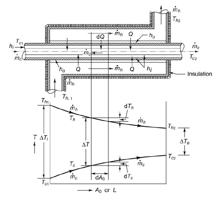
Fig4.11 Parallel flow heat exchanger
An insulated double pipe parallel flow heat exchanger along with the temperature profiles is shown in Fig. The temperatures of the fluids vary from point to point as heat is transferred from the hot to the cold fluid.
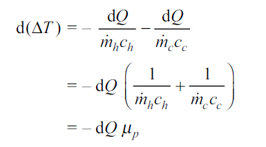
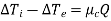
Let us consider a differential surface area d A0 (= D0 dx) of the heat exchanger where dQ amount of heat is transferred, the hot fluid temperature decreases by dTh and the cold fluid temperature increases by dTc. By writing an energy balance,
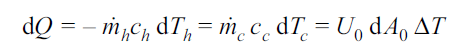
…(4.4)
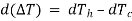
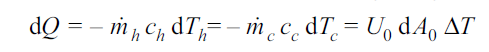
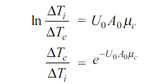
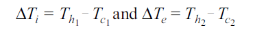
where  T = Th – Tc, Th and Tc being the mean temperatures of the hot and cold fluids at that section respectively. This temperature difference
  T between the two fluids changes from
  Ti at inlet to
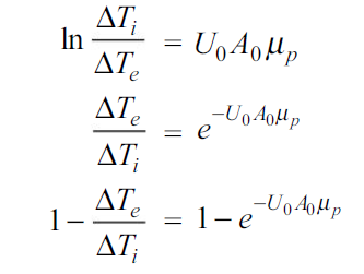
  Te at exit of the heat exchanger. Hence,

and
…(4.5)
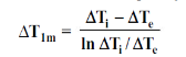
From 4.4 and 4.5

…(4.6)
Where
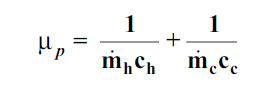
By integrating 4.6 with  being constant
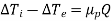
…(4.7)
From 4.4 and 4.6
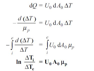
…(4.8)
From Eq. 4.7 and 4.8
Counter flow heat exchanger
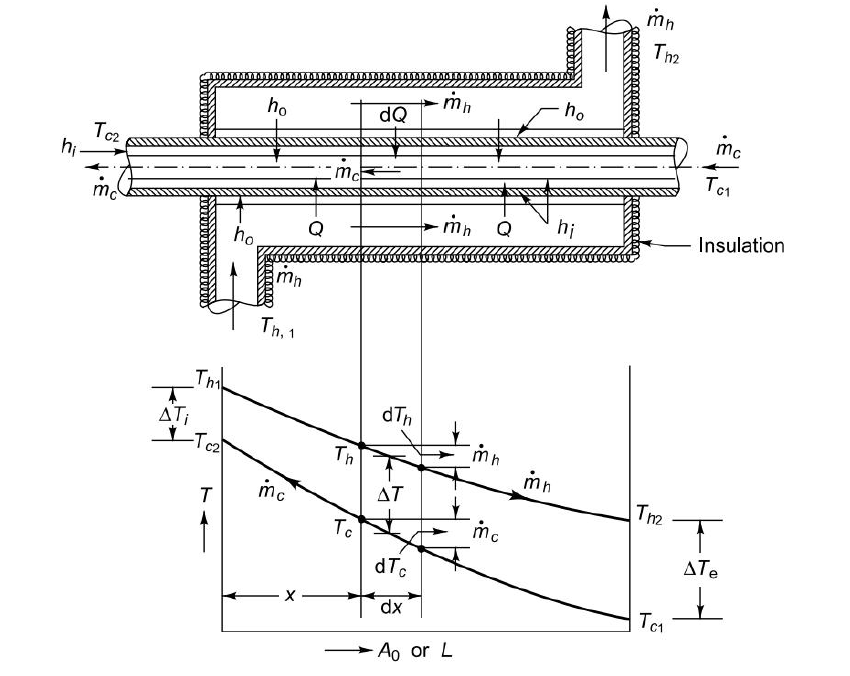
Fig4.12 Counter flow heat exchanger
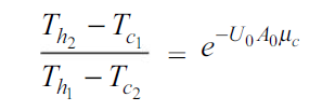
Figure shows an insulated double pipe counter flow heat exchanger along with the temperature profiles. The energy balance for the differential surface area dA0 ( D0 dx) gives
…(4.9)
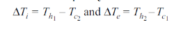
where both the hot and cold fluids undergo temperature decreases dTh and dTc (both being negative) in flowing the distance dx.

…(4.10)
Where
By integrating 4.10 with  being constant
…(4.11)
From 4.9 and 4.10
…(4.12)
From Eq. 4.11 and 4.12
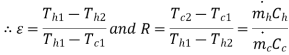
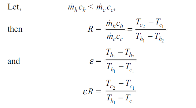
The Effectiveness-NTU method
To obtain the solution of this problem by the LMTD method, a trial-and-error approach has to be attempted. The method is quite tedious and can be avoided by following an alternative direct method called the effectiveness-NTU method.
The term effectiveness  of a heat exchanger is defined as
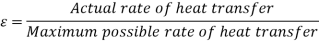

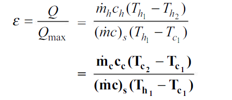
…(4.13)
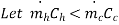
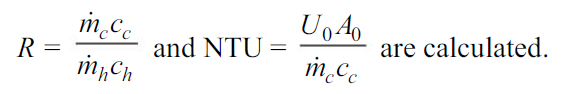
where subscript “s” denotes the smaller of the two heat capacity rates  and
and  , or Cmin. The maximum possible heat transfer depends on one of the fluids undergoing the maximum possible change in temperature and that will be the fluid which will have the minimum value of heat capacity rate.
Thus, if 

…(4.14)
And if 

…(4.15)
Thus effectiveness can also defined as
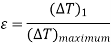
Where  is larger of two temperature differences
 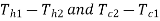 and
and  is maximum possible temperature rise or fall which is
Another important term in  -NTU method is heat capacity ratio. It is defined as ratio of minimum heat capacity rate to maximum heat capacity rate out of two fluids.
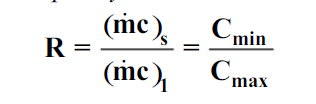
…(4.16)
where the subscripts “s” and “1” refer to the smaller and the larger of the two values of and
and  .
.
Value of  and R varies between 0 and 1.
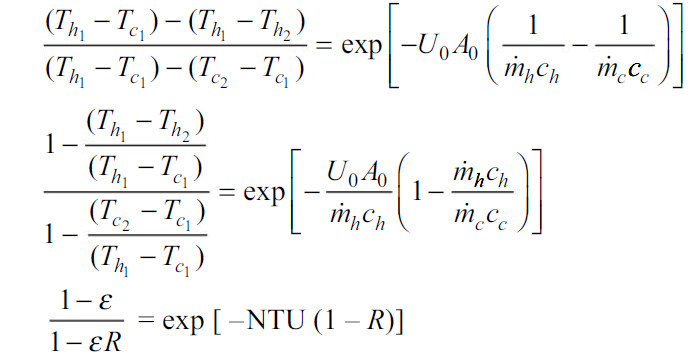
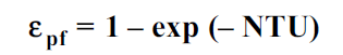
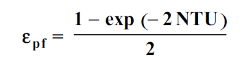
Analysis of parallel flow heat exchanger
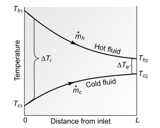
Fig4.13 Parallel flow heat exchanger
From Eq. 4.8
But

Hence
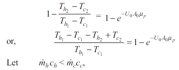
…(4.17)
Eq. 4.17 becomes
…(4.18)
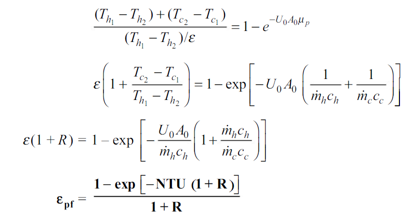
Where NTU is number of transfer units and is equal to
( c)s or Cmin being equal to
  in this case. NTU gives a measure of the size of the heat exchanger.
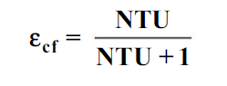
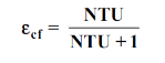
Analysis counter flow heat exchanger
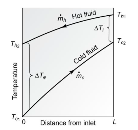
Fig4.14 Counter flow heat exchanger
From Eq.4.12
For counter flow heat exchanger
…(4.19)
…(4.20)
Also,
Hence 4.19 can be written as

Let RHS=K
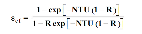

…(4.21)
Steps in analysis by Effectiveness-NTU method
The quantities  and
and  are computed.
if 
Then effectiveness of can found by Eq.4.18and 4.21
Since
From this  can be found out and
  can found by Eq.4.8
Special cases
Eq. 4.18 becomes
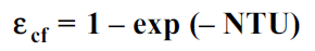
And Eq.4.21 becomes
Eq. 4.18 becomes
And Eq.4.21 becomes
Selection of heat exchangers
Selection of heat exchangers depends on following criteria:
Important Formulae
Overall heat transfer coefficient |
|
Overall heat transfer coefficient with fouling factor |
|
LMTD for parallel flow |
where
|
LMTD for counter flow |
Where
|
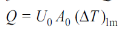
Heat exchange by LMTD method |
|
Effectiveness of parallel flow heat exchanger |
|
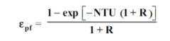
Effectiveness of counter flow heat exchanger |
|

References


