Unit 2
Impact of Jets
Water flows in the pipeline under pressure. If a nozzle is fitted at the end of the pipe, the water comes out of the pipe with a very high velocity in the form of a jet. This high velocity jet can be used for various applications as given below:
- In case the jet strikes a fixed or moving plant, the energy of the jet this converted to produce a force on the plate. This force exerted by the jet on the plate is called impact of jet. The magnitude of this force can be found by using Newton’s second law of motion.
2. When the jet leaves the nozzle, it exerts a reactive force on the nozzle itself which is in accordance with Newton’s third law of motion. This reactive force acts in the direction opposite to that of the jet. And pushes the body attached to the nozzle backwards. This is known as Jet Propulsion.
Impulse momentum principle
The momentum of fluid is defined as the product of mass and its velocity. Therefore,
Momentum M = Mass, m X Velocity, V --------- (1)
According to Newton's second law of motion the rate of change of momentum is directly proportional to external force acting on the body.
F α dM/dt
F = gc X dM/dt ---------(2)
Where, gc is the constant of proportionality
From (1) and (2) and product rule of differentiation, we can substitute and rewrite (2) as
F = d (m.V)/dt = [m.dV/dt + V.dm/dt]
In hydrodynamic machines, dm/dt = 0, since there is no change in mass with respect to time.
F = m.dV/dt = m.a ----------(3)
However, in fluid mechanics hey we are confirmed with constant mass flow of a continuous fluid, therefore, dm/dt = 0
F = m dV/dt = (m/t). (V2 - V1) ---------- (4)
Where, V2 and V1 are the velocity of the fluid at section sections 2 and 1 respectively.
Product (F.t) is called as Impulse.
(m/t) = mass flow rate of fluid which we will here forth denote using ‘mf‘
And mf = µ.Q where, µ is the density of the fluid and Q is the volume flow rate.
Therefore (4) can now be rewritten as
F = µ.Q (V2 - V1) ---------(5)
Equation (5) represents the force F exerted by the fluid on the body.
Consider a jet of water of cross-sectional area A moving with a velocity V which impinges on fixed plate.
Q = A.V
mf = µ. Q = µ. A.V
Jet may strike fixed plate either in normal direction or at some angle. It is hey assumed that the plate is perfectly smooth that is there is no friction between the jet and plate and there is no loss of energy during impact of jet and the velocity of jet is uniform throughout.
2.2.1 When the fixed plate is normal to jet
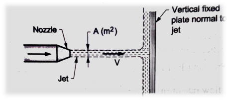
Consider fluid jet striking a fixed plate normal to the jet as shown in the figure above. Since the plate is fixed, its velocity is zero. When the jet strikes the plate, its momentum is completely destroyed by the application of force and its final velocity becomes zero. Therefore, force acting on the plate in the direction normal to the plate can be determined by using impulse momentum equation.
F = mf (V1 - V2) = µ. A.V (V1 - V2)
V1 is the absolute velocity of jet in X-direction before impact which is V and V2 is the absolute velocity of jet in X-direction after the impact which is zero in this case. Therefore,
F = µ. A.V (V) = µ. A.V2
2.2.2 When the fixed plate is inclined to jet
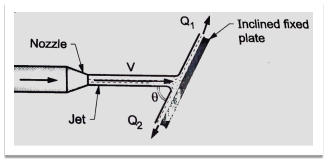
Consider a fixed plate inclined at an angle θ as shown in the figure above.
Resolution of velocity normal and parallel to the plate is shown in the figure below
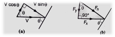
Velocity of jet normal to plate = V sin θ
Final velocity normal to jet = 0
A) Normal force on plate
Using impulse momentum equation, we get,
Fn = µ. A.V (V sin θ - 0) = µ. A.V2 sin θ
B) Force on plate in XX&YY direction
By revolving the normal force in XX&YY directions we get
Fx = Fn sin θ
= µ . A.V2 sin θ. Sin θ
= µ . A.V2 sin 2 θ
Fy = Fn cos θ
= µ . A.V2 sin θ. Cos θ
Work done on the plate by the jet is zero in both the cases since the plate is stationary.
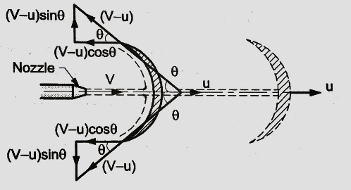
2.3.1 When jet strikes at the center of symmetrical curved plate
Consider fluid jet of cross-sectional area A and velocity V striking smooth stationary curved plate at centre as shown in the figure below.
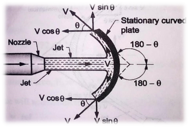
The jet comes out at the same velocity V along the curved surface of the plate.
Component of velocity in XX and YY directions are Vcos θ and Vsin θ respectively.
Mass flow rate, mf = µ A.V
Initial velocity of jet in xx direction,
V1 = V
Final velocity of jet in xx direction,
V2 = - Vcos θ
By impulse momentum equation,
F = mf (V1 - V2)
For XX direction
Fx = µ A.V (V - (-V cos θ))
Fx = µ A.V2 (1 + cos θ)
Since the jet is travelling horizontally, V1y = 0, and V2y = V sin θ
Fy = µ A.V (V1y - V2y) = µ A.V (0 – V sin θ) = - µ A.V2 sin θ
Negative sign indicates the force is in downward direction.
2.3.2 When jet strikes an unsymmetrical curved plate at one end tangentially
Consider a jet of velocity V striking tangentially do an unsymmetrical curved plate as shown in the figure below.
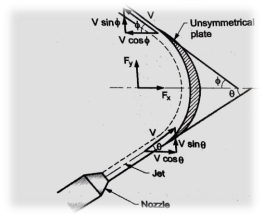
Let plate tip angles be Θ and Φ.
Initial velocity components at inlet are:
Vx = V cos θ, Vy = V sin θ
Final velocity components at outlet are:
Vx = V cos Φ, Vy = V sin Φ
And mf = µ.A.V
Using impulse momentum equation Hey the force exerted on plate in XX and YY directions will be:
Fx = µ A.V. [ Vcos θ - (-Vcos Φ)] = µ A.V2 [ cos θ + cos Φ]
Fy = µ A.V. [ Vsin θ - Vsin Φ] = µ A.V2 [ sin θ - sin Φ]
No work is done on the plate since it is stationary.
2.4.1 force on moving flat plate in direction of jet
Figure below shows a horizontal fluid jet striking a vertical plate moving with a uniform velocity away from the jet in horizontal direction
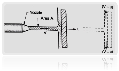
Let, V = Absolute velocity of jet
A = Cross-sectional area of jet
u = Absolute velocity of plate
Relative velocity of jet wrt plate = (V - u)
Mass flow rate of water striking the plate mf = µ.A (V - u)
Therefore, force exerted by jet normal to plate,
Fn = µ.A (V – u) [(V – u) - 0] = µ.A (V - u)2
Efficiency of system, η
Efficiency of the system is defined as the ratio of work done (W.D.) by the jet to the kinetic energy (K.E.)
Supplied
K.E. Of jet = ½ mf V2 = ½ µ.A.V. V2 = ½ µ.A.V3
η = W.D / K. E = [µ.A (V - u). u] / [½ µ.A.V3 ] = 2/V3 [ V2 u – 2Vu2 + u3 ]
Condition for maximum efficiency
For a given jet velocity, the condition for maximum is that the differentiation of efficiency wrt plate velocity, u, should be 0.
Therefore, differentiating above derived equation wrt u and equating to 0,
d/du {2/V3 [ V2 u – 2Vu2 + u3] } = 0
2/V3 [ V2 – 4Vu + 3u2 ] = 0
But
2/V3 = 0 is not possible since it implies that V = 0.
Therefore, [ V2 – 4Vu + 3u2 ] = 0
Solving the above quadratic equation by factorisation, we get,
V = u OR V = 3u.
Again, if V = u, the W.D. Would be zero.
Therefore, condition for maximum efficiency is V = 3u.
Substituting this in equation for efficiency,
η max = 8/27
2.4.2 Force on moving inclined plate in direction of jet
Consider a jet of cross-sectional area A and velocity V striking a moving inclined plate which moves with velocity u. Θ represents angle between the plate and jet as shown in the figure below.
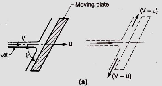
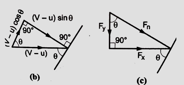
Components for velocity in normal and tangential direction are also shown in figure b and c.
Relative velocity of jet of water striking the plate = V – u
Mass flow rate, mf = µ.A.(V - u)
Force of jet on plate in normal hey direction,
Fn = µ.A.(V - u) [ (V – u)sin θ – 0 ] = µ.A.(V - u)2 sin θ
Component or normal force in X direction and Y direction are shown in the figure c.
Fx = µ.A.(V - u)2 sin 2 θ
Fy = µ.A.(V - u)2 sin θ . Cos θ
Rate of work done by jet on plate in X direction
W = Fx u = µ.A.(V - u)2 sin 2 θ * u
Consider the case of continuous series of plates at a fixed distance apart as shown in the figure below.
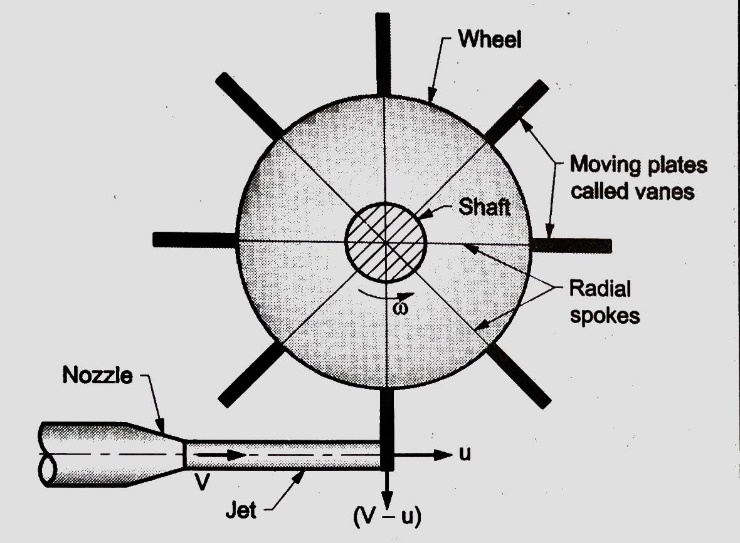
All the plate for moving in the same direction of the jet with velocity u then such system can be put to practical use. In the above figure, the plates are called vanes and are fixed on moving wheel in the radial direction along its circumference. The jet strikes vanes tangentially.
Because series of moving radial plates are available continuously to intercept the jet, the mass flow rate of water striking the plates will be,
mf = µ . A . V
Force on plate, F = mf [(V - u) - 0] = µ . A . V (V - u)
Rate of WD, W = F.u = µ . A . V (V - u) u
KE supplied = ½ µ . A . V. V2 = ½ µ . A . V3
Efficiency of the system, η = WD / KE = [µ. A. V (V - u)] / [½ µ. A. V3] = 2/V2 (V - u)u
Condition for maxiµm efficiency, ηmax , is differentiation of efficiency wrt plate velocity should be 0.
That is, dη/du = 0
Therefore, d/du [2/V2 (V - u)u] = 0.
2/V2 [V – 2u] = 0
Therefore, V = 2u.
On substituting the condition of maximum efficiency, we get ηmax = 0.5 or 50%
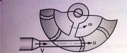
2.6.1 Curved Vane moving in the direction of jet
Consider a jet of water of A and velocity V strikes a single symmetrical moving curved vane at velocity u as shown in the figure below
Jet leaves the vane in tangential direction at angle θ from horizontal at relative velocity (V - u).
Mass flow rate of jet of water striking the vane, mf = µ . A . (V – u)
Normal force on vane, Fn = µ . A . (V – u) [ (V - u) - {- (V - u)cos θ} ]
= µ . A . (V – u)2 (1 + cos θ)
Rate of WD, W = Fn u
= µ . A . (V – u)2 (1 + cos θ) u
KE supplied by jet, KE = ½ µ . A . V3
Efficiency of system η = WD / KE
= 2/V3 (V – u)2 (1 + cos θ) u
Condition for maximum efficiency is differentiation of efficiency wrt vane velocity, u, should be 0.
Therefore, d η / du = 0
Therefore, d/du (2/V3 (V – u)2 (1 + cos θ) u) = 0
On solving the above equation, we get, V = 3u.
On substituting in the equation for efficiency, we get ηmax = 8/27 (1 + cos θ)
2.6.2 Series of moving vanes in direction of jet
Mass flow rate striking the vanes, mf = µ . A . V
Normal force exerted on vanes,
Fn = µ . A . V [ (V - u) - {- (V - u)cos θ} ]
= µ . A . V (V – u) (1 + cos θ)
Rate of WD, W = Fn u
= µ . A . V (V – u) (1 + cos θ) u
KE supplied by jet, KE = ½ µ . A . V3
Efficiency of system η = WD / KE
= 2/V2 (V – u) (1 + cos θ) u
Condition for maximum efficiency is differentiation of efficiency wrt vane velocity, u, should be 0.
Therefore, d η / du = 0
Therefore, d/du (2/V2 (V – u) (1 + cos θ) u) = 0
On solving the above equation, we get, V = 2u.
On substituting in the equation for efficiency, we get ηmax = 1/2 (1 + cos θ)
2.6.3 Impact of jet on unsymmetrical moving curved vane when the jet strikes on one tip of the vane tangentially and leaves at the other
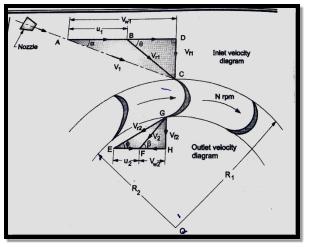
Consider a jet of water leaving the nozzle at absolute velocity V1 and vane moves with velocity u as shown in the figure
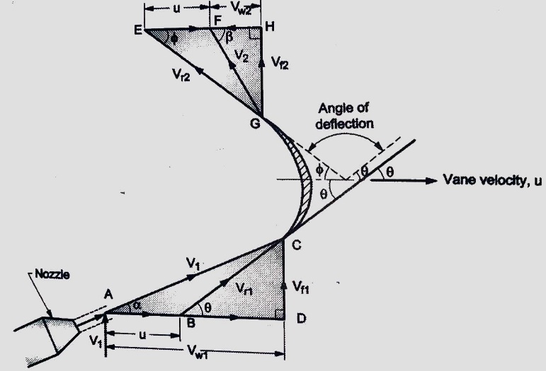
The jet will enter at relative velocity, Vr1 = V1 - u , tangentially at inlet angle of vane θ.
Let,
V1 = absolute velocity of jet;
u = vane velocity at inlet of vane
α = exit angle of nozzle
Θ = inlet angle of moving vane
Φ = exit angle of moving vane
β = angle at which the jet leaves the vane
Vr1 = relative velocity at inlet
V2 = absolute velocity of jet at outlet
Vr2 = relative velocity at outlet of vane
All angles are measured with direction of motion of vane.
Vw and Vf, are the components of absolute velocity in the direction of motion of vane and normal to it respectively. Vw is called velocity of whirl or tangential velocity and Vf is called velocity of flow. Therefore,
Vw1 = Velocity of whirl at inlet
Vw2 = Velocity of whirl at outlet
Vf1 = Velocity of flow at inlet
Vf2 = Velocity of flow at outlet.
Inlet velocity diagram
Draw AB to represent the vane velocity u in magnitude and direction.
Draw AC to represent jet velocity V1 at an angle α in magnitude and direction.
Then vector BC = Vr1, which is equal to (V1 - u) represents the relative velocity at inlet which strikes the vane tangentially at an angle theta.
Vw1 and Vf1 are the components of V1 which represent whirl velocity and velocity of flow at inlet.
Vw, whirl component of velocity is responsible to produce the driving force while the flow component of velocity. Vf is responsible for flow of water.
Outlet diagram
The water will pass over the vane and leave tangentially with relative velocity Vr2 at an outlet angle of phi. The absolute velocity of jet V2 , at outlet can be determined by vector sum of Vr2 and u. It leaves the vane at angle β.
Vw2 and Vf2 are components of absolute velocity V2, in the direction of motion of vane and normal to it respectively.
If friction between water and vane is neglected, then
Relative velocity at outlet, Vr2 = Relative velocity at inlet, Vr1
Mass flow rate of water striking the vane, mf = µ A V
Force exerted in direction of motion of vane, Fx.
Force Fx, is produced due to change in whirl velocity. Therefore, normal force.
Fn = Fx = µ A V (Vw1 - Vw2)
But Vw2 is negative to Vw1 when β<90°. Therefore, magnitude of force,
Fx = µ A V (Vw1 + Vw2)
When β = 90°, Vw2 = 0
When β>90°, Vw2 is positive and
Fx = µ A V (Vw1 - Vw2)
Rate of WD, W = µ A Vr1 (Vw1 + Vw2) u
Efficiency of jet, η = WD / KE = [µ A Vr1 (Vw1 + Vw2) u]/[½ µ A V13]
= 2/V13 [Vw1 + Vw2 ] Vr1 u
2.6.3 Force exerted on a series of moving radial curved vanes
For radial curved vane, the radius of vane at inlet and outlet is different. Hence blade velocity u will be different at inlet and outlet.
Consider a series of radial vanes mounted on a wheel have shown in the figure
Let,
N = Speed of the wheel in rpm,
R1 = Radius of wheel at inlet,
R2 = Radius of wheel at outlet,
Angular speed of wheel, ω = 2πN/60 rad/s
Therefore, blade velocity at inlet, u1 = ω R1
Blade velocity at outlet, u2 = ω R2
Water may flow radially on vanes either inwards or outwards depending upon whether the water enters the outer or inner periphery of the wheel.
Mass of water striking the series of vanes per second, mf = µ AV
(where. A = area of jet and V, = velocity of jet)
Rate of momentum of water striking the vanes in tangential direction at inlet = mf Vw1 (where, Vw1=V1cos α) and the angular momentum is the moment of the rate of momentum
Rate of angular momentum of jet at inlet = mf Vw1 R1=µ AV1 Vw1 R1.
Similarly, Rate of angular momentum of jet at outlet = mf Vw2 R2, = µ AV1 Vw2 R2.
Torque exerted on wheel, T
The rate of change of angular momentum is defined as torque. Therefore,
Torque, T = Rate of angular momentum at inlet - Rate of angular momentum at outlet
T = µ AV1 Vw1 R1 - µ AV1 Vw2 R2 = µ A V1 (Vw1 R1 + Vw2 R2)
Rate of work done, W = T ω = µ A V1 (Vw1 R1 + Vw2 R2) ω = µ A V1 (Vw1 u1 + Vw2 u2)
Efficiency of system , η = W/KE
= {µ A V1 (Vw1 u1 + Vw2 u2)} / {½ µ A V13}
= 2/V12 (Vw1 u1 + Vw2 u2)
- Jet propulsion means propulsion or movement of the bodies such as ships, rockets, aircrafts etc. with the help of jet.
- The reaction of the jet coming out from the nozzle attached to the bodies is used to move the bodies.
- According to Newton’s third law of motion, every action there is an equal and opposite reaction.
- The fluid coming out from the nozzle exerts a force on the nozzle in the opposite direction.
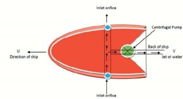
Jet Propulsion of Ships
By the application of jet propulsion, the ship is driven through water. Jet of water is discharged at the back of ships, exerts a propulsive force on the ship. The ship carries a centrifugal pump which draws a water from surrounding sea. The water is discharged through the orifice which is fitted at the back of the ship in the form of jet.
Case-1 Jet propulsion of the ship, when inlet orifice is at right angle to the direction of motion of ship
V = velocity of jet coming out at the back of ship
U = velocity of ship
V and U are in opposite direction.
Relative velocity of jet w.r.t ship = V +U = Vr
Mass of jet issuing from nozzle at the back of ship = ρ a (V +U)
Force exerted by the jet on the ship = mass of water issuing/s x change in velocity
F = ρa (V +U) x (Vr - u ) = ρa (V +U) x ((V +U) –u)
F = ρaV (V +U)
Work done = F x u = ρaV (V +U) x u
Case-2 Jet propulsion of the ship, when inlet orifice facing the direction of motion of ship
Water enters the orifice with the same velocity as velocity of ship.
KE supplied by jet = ½ x mass of water x change in velocity
= ½ ρ a Vr (Vr2 - u2 )
= ½ ρ a (V + u) ((V+u)2 - u2)
Efficiency of propulsion
Efficiency of propulsion = (WD by jet) / (KE supplied by jet)
= 2u / (V + 2u)
References: -
Text Books:
1. G. T. Mase, R. E. Smelser and G. E. Mase, Continuum Mechanics for Engineers, Third
Edition, CRC Press,2004.
2. Y. C. Fung, Foundations of Solid Mechanics, Prentice Hall International, 1965.
3. Lawrence. E. Malvern, Introduction to Mechanics of a Continuous Medium, Prentice Hall
International, 1969.
4. Hydrantic Machine by Jagdish Lal
5. Hydraulics & Hydraulic Machines by Vasandari
6. Hydrantic Machine by RD Purohit


