Unit– 2
Beams and types transverse loading on beams
Beam:
Beam is a structural member used to resist the applies load. Generally, beam is used to resist the shear force, vertical load and bending moment. Beam is a flexible member which can resist the compression and tension force. For example, in reinforcement, steel have ability to resist the tension. While concrete used to resist the compression force. There is different type of beam, based on shape, based on geometry, based on supports, based on equilibrium conditions. The types of beam are given in detail which is given below:
There are two types of loading on beam-
Transverse loading is a load applied vertically to the plane of the longitudinal axis of a configuration, such as a wind load. It causes the material to bend and rebound from its original position, with inner tensile and compressive straining associated with the change in curvature of the material.
Transverse loading is also known as transverse force or crosswise force.
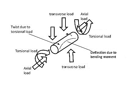
Fig. Transverse loading
Shear force:
Shear force is a force component that is parallel to a cross sectional area of interest. This force is trying to cut the part at that cross-sectional area.
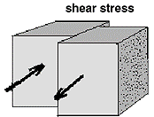
Fig. Shear stress
For example, in above figure the contact surface between two surfaces are applying forces along the contact surface. These are shear forces.
Bending moment
Assumptions:
The constraints put on the geometry would form the assumptions:
1. Beam is initially straight, and has a constant cross-section.
2. Beam is made of homogeneous material and the beam has a longitudinal plane of symmetry.
3. Resultant of the applied loads lies in the plane of symmetry.
4. The geometry of the overall member is such that bending not buckling is the primary cause of failure.
5. Elastic limit is nowhere exceeded and ‘E' is same in tension and compression.
6. Plane cross - sections remains plane before and after bending.
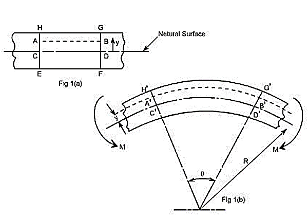
Fig. Bending moment diagram
Let us consider a beam initially unstressed as shown in fig 1(a). Now the beam is subjected to a constant bending moment (i.e., ‘Zero Shearing Force') along its length as would be obtained by applying equal couples at each end. The beam will bend to the radius R as shown in Fig 1(b) As a result of this bending, the top fibers of the beam will be subjected to tension and the bottom to compression it is reasonable to suppose, therefore, that somewhere between the two there are points at which the stress is zero.
The locus of all such points is known as neutral axis the radius of curvature R is then measured to this axis. For symmetrical sections the N. A. is the axis of symmetry but whatever the section N. A. will always pass through the centre of the area or centroid.
The above restrictions have been taken so as to eliminate the possibility of 'twisting' of the beam.
Based on support:
The types of beam based on support are:
Simply supported beam
It is the type of beam in which on end is roller and other end is pinned. The simply supported beam is the simplest structure element because the both ends are rest on support.in this type of beam the one end is free to rotate and have not any ability to resist moment.
Continuous beam:
Continuous beam is the type of beam in which have more than two supports distributed through its entire length.
Over hanging beam:
Over hanging beam is the type of beam in which both or single end are extended beyond the support. It may have any number of supports but the condition the one or both end should be extended. The both ends in over hanging beams are roller support.
Double over hanging:
In this type of beam the both ends of beam are over hanging beyond the supports is known as double over hanging beam. there is difference between over hanging beam and double over hanging beam. In over hanging beam the one side is over hanging while in double over hanging the both side is over hanging beyond the supports.
Cantilever beam:
Cantilever beam is the type of beam in which one end is fix and one is free. This beam can resist the shear force and bending moment. Cantilever beam is mostly used in buildings, bridges, and trusses etc.
Fixed beam:
In this type of beam the both end is fixed. Fixed beam resist the vertical load, horizontal load and also moment. This type of beam is used in building, trusses or other structures.
Trussed beam:
Trussed beam is the type of beam in which cables or rod are added for getting the more strength to form a truss.
Based on equilibrium condition:
The type of beam based on equilibrium condition are given below:
Statically determinant:
A beam is said to be determinant if it can be analyzed by basic equilibrium condition. These three conditions should be obeying then it will be statically determinant. The three condition are as follow:
The example of statically determinant beams is cantilever beam, simply supported beam.
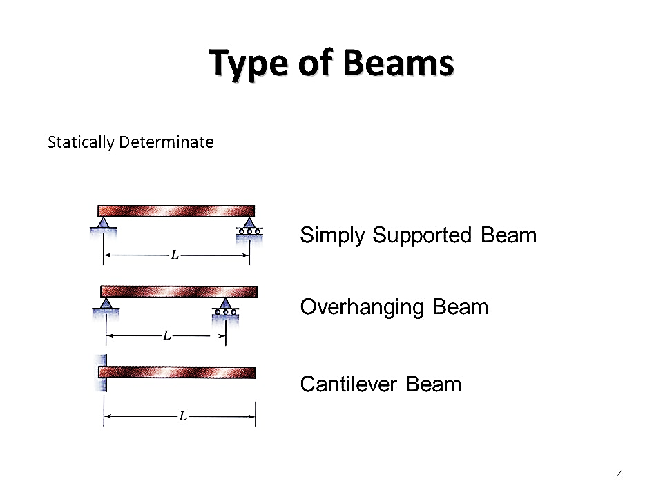
Fig. Statically determinant beam
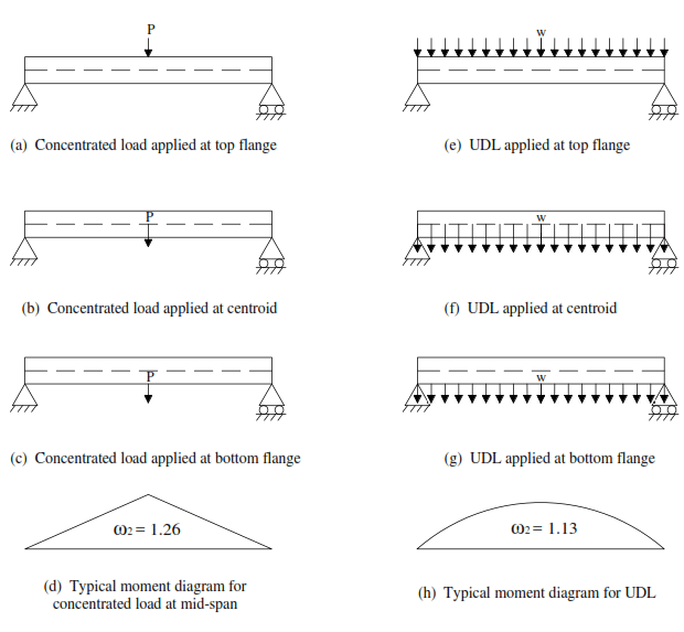
Fig. Simply supported beam under concentrated load
Statically indeterminant:
A beam is said to be in determinant if it can be analyzed by basic equilibrium condition. These three conditions should be obeying then it will be statically in determinant. The end can be found by using basic equilibrium equation and also addition of other conditions like strain energy method, virtual energy method etc. the example statically in determinant beam is continuous beam, fixed beam.
When a beam having an arbitrary cross section is subjected to a transverse loads the beam will bend. In addition to bending the other effects such as twisting and buckling may occur, and to investigate a problem that includes all the combined effects of bending, twisting and buckling could become a complicated one. Thus, we are interested to investigate the bending effects alone, in order to do so, we have to put certain constraints on the geometry of the beam and the manner of loading.
Assumptions:
The constraints put on the geometry would form the assumptions:
1. Beam is initially straight, and has a constant cross-section.
2. Beam is made of homogeneous material and the beam has a longitudinal plane of symmetry.
3. Resultant of the applied loads lies in the plane of symmetry.
4. The geometry of the overall member is such that bending not buckling is the primary cause of failure.
5. Elastic limit is nowhere exceeded and ‘E' is same in tension and compression.
6. Plane cross - sections remains plane before and after bending.

Fig 1 (a, b)
Let us consider a beam initially unstressed as shown in fig 1(a). Now the beam is subjected to a constant bending moment (i.e., ‘Zero Shearing Force') along its length as would be obtained by applying equal couples at each end. The beam will bend to the radius R as shown in Fig 1(b) As a result of this bending, the top fibers of the beam will be subjected to tension and the bottom to compression it is reasonable to suppose, therefore, that somewhere between the two there are points at which the stress is zero.
The locus of all such points is known as neutral axis the radius of curvature R is then measured to this axis. For symmetrical sections the N. A. is the axis of symmetry but whatever the section N. A. will always pass through the centre of the area or centroid.
The above restrictions have been taken so as to eliminate the possibility of 'twisting' of the beam.
Concept of pure bending:
Loading restrictions:
As we are aware of the fact internal reactions developed on any cross-section of a beam may consists of a resultant normal force, a resultant shear force and a resultant couple. In order to ensure that the bending effects alone are investigated, we shall put a constraint on the loading such that the resultant normal and the resultant shear forces are zero on any cross-section perpendicular to the longitudinal axis of the member,
That means F = 0
Since dM/dX =0 or M = constant.
Thus, the zero-shear force means that the bending moment is constant or the bending is same at every cross-section of the beam. Such a situation may be visualized or envisaged when the beam or some portion of the beam, as been loaded only by pure couples at its ends. It must be recalled that the couples are assumed to be loaded in the plane of symmetry.
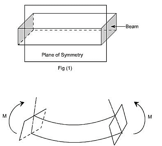
Fig 2
When a member is loaded in such a fashion it is said to be in pure bending. The examples of pure bending have been indicated in EX 1and EX 2 as shown below:
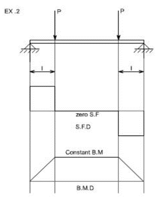
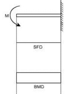
Fig 3
When a beam is subjected to pure bending are loaded by the couples at the ends, certain cross-section gets deformed and we shall have to make out the conclusion that
1. Plane sections originally perpendicular to longitudinal axis of the beam remain plane and perpendicular to the longitudinal axis even after bending, i.e. the cross-section A'E', B'F' (refer Fig 1(a) ) do not get warped or curved.
2. In the deformed section, the planes of this cross-section have a common intersection i.e., any time originally parallel to the longitudinal axis of the beam becomes an arc of circle
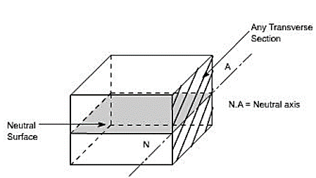
Fig 4
We know that when a beam is under bending the fibres at the top will be lengthened while at the bottom will be shortened provided the bending moment M acts at the ends. In between these there are some fibres which remain unchanged in length that is they are not strained, that is they do not carry any stress. The plane containing such fibres is called neutral surface.
The line of intersection between the neutral surface and the transverse exploratory section is called the neutral axis Neutral axis (N A).
Bending Stresses in Beams or Derivation of Elastic Flexural formula:
In order to compute the value of bending stresses developed in a loaded beam, let us consider the two cross-sections of a beam HE and GF, originally parallel as shown in fig 1(a).when the beam is to bend it is assumed that these sections remain parallel i.e. H'E' and G'F', the final position of the sections, are still straight lines, they then subtend some angle θ.
Consider now fiber AB in the material, at a distance y from the N.A, when the beam bends this will stretch to A'B'
Therefore strain in fiber AB =Change in length /original length
=A’B’-AB/AB
But from fig 1 (a,b)
AB=CD and CD=C’D’
=A’B’-C’D’/C’D’
Since CD and C'D' are on the neutral axis and it is assumed that the Stress on the neutral axis zero. Therefore, there won't be any strain on the neutral axis
=(R+y)θ-Rθ / Rθ
=(Rθ+yθ-Rθ / Rθ
=y/R
However stress/strain =E
Where E=Y oung modulus of elasticity
Therefore equating the two strains as obtains from the two relation i.e.
σ/E = y/R or σ/y = E/R…1
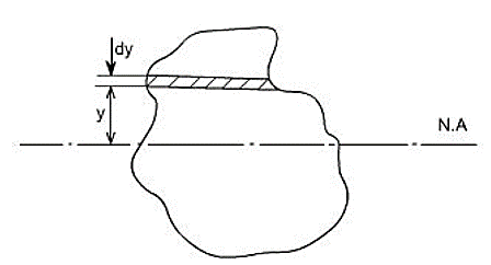
Fig. 5
Consider any arbitrary a cross-section of beam, as shown above now the strain on a fibre at a distance ‘y' from the N.A, is given by the expression
σ= E.y/R
If the shaded strip of area dA then the force on the strip is
F = σδA = (E/R) y.δA
Moment about the neutral axis would be F.y = (E/R) y2 δA
The total moment for the whole cross section is therefore equal to
M=∑ (E/R) y2 δA = E/R ∑y2 δA
Now the term ∑y2 δA is the property of the material and is called as a second moment of area of the cross-section and is denoted by a symbol I.
Therefore
M= (E/R) I…..2
Combining equation 1 and 2 we get
M/I = σ/y = E/R
This equation is known as the Bending Theory Equation. The above proof has involved the assumption of pure bending without any shear force being present. Therefore this termed as the pure bending equation. This equation gives distribution of stresses which are normal to cross-section i.e. in x-direction.
Key takeaways
1) M/I = σ/y = E/R This equation is known as the Bending Theory Equation
2) There are some fibres which remain unchanged in length that is they are not strained, that is they do not carry any stress. The plane containing such fibres is called neutral surface.
How to Calculate Bending Stress in Beams
We will understand bending stresses by taking simple example. we will look at how to calculate the bending stress of a beam using a bending stress formula that relates the longitudinal stress distribution in a beam to the internal bending moment acting on the beam’s cross-section.
We assume that the beam’s material is linear-elastic (i.e. Hooke’s Law is applicable). Bending stress is important and since beam bending is often the governing result in beam design, it’s important to understand.
Let’s look at an example. Consider the I-beam shown below:
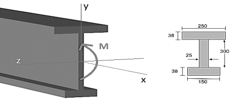
At some distance along the beam’s length (the x-axis), it is experiencing an internal bending moment (M) which you would normally find using a bending moment diagram. The general formula for bending or normal stress on the section is given by:
σ bend = My/I
Where M= The internal bending moments about the section neutral axis
y=the perpendicular distance from the neutral axis to a point on the section
I= The moment of inertia of the section area about the neutral axis
Given a particular beam section, it is obvious to see that the bending stress will be maximized by the distance from the neutral axis (y). Thus, the maximum bending stress will occur either at the TOP or the BOTTOM of the beam section depending on which distance is larger:
σ bend max= Mc/I
Where c=the perpendicular distance from the neutral axis to a farthest point on the section
Lets’s consider the real example of our I-beam shown above. In our previous moment of inertia tutorial, we already found the moment of inertia about the neutral axis to be I = 4.74×108 mm4. Additionally, in the centroid tutorial, we found the centroid and hence the location of the neutral axis to be 216.29 mm from the bottom of the section. This is shown below:
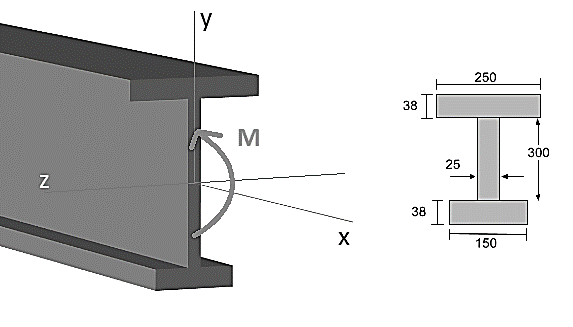
Fig 7
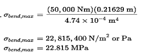
Obviously, it is very common to require the MAXIMUM bending stress that the section experiences. For example, say we know from our bending moment diagram that the beam experiences a maximum bending moment of 50 kN-m or 50,000 Nm (converting bending moment units). Then we need to find whether the top or the bottom of the section is furthest from the neutral axis. Clearly, the bottom of the section is further away with a distance of c = 216.29 mm. We now have enough information to find the maximum stress using the bending stress formula above:
σ bend max= Mc/I
M=50KM = 50,000 Nm
C=216.29mm = 0.21629m (bottom)
I = 4.74 X 108mm4 =4.74 x 10⁴ m4
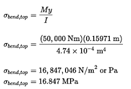
Similarly, we could find the bending stress at the top of the section, as we know that it is y = 159.71 mm from the neutral axis (NA):
The last thing to worry about is whether the stress is causing compression or tension of the section’s fibers. If the beam is sagging like a “U” then the top fibers are in compression (negative stress) while the bottom fibers are in tension (positive stress). If the beam is sagging like an upside-down “U” then it is the other way around: the bottom fibers are in compression and the top fibers are in tension.
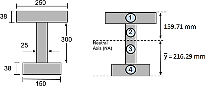
Fig.8
Section modulus
The maximum bending stress in a beam is calculated as σb = My / Ic, where y is the distance from the neutral axis to the extreme fiber, Ic is the centroidal moment of inertia, and M is the bending moment.
The section modulus combines the y and Ic terms in the bending stress equation:
Z = Ic / y
Using the section modulus, the bending stress is calculated as σb = M / Z. The utility of the section modulus is that it characterizes the bending resistance of a cross section in a single term. This allows for optimization of a beam's cross section to resist bending by maximizing a single parameter.
Properties of Common Cross Sections
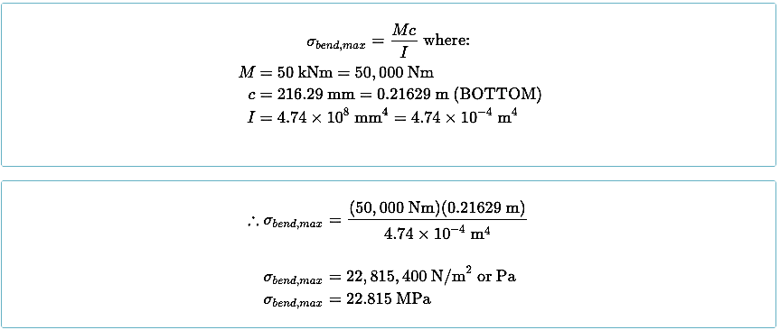

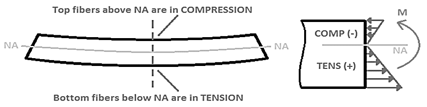

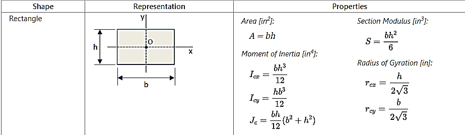
Fig. Shear stress distribution
A point load is an area where the structure is transferred vertically to the foundation, a horizontal beam, or a bearing wall. These vertical loads are typically picked up by studs or steel columns.
A uniformly distributed load is one whose weight is evenly distributed over the entire surface of the rack's beams or deck.
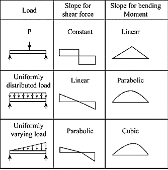
Fig. Slopes for various types of loading
References


