Unit-2
Measurement of Voltage
2.1.1. Moving Iron
The most common ammeters and voltmeters for laboratory or switch board used at power frequencies are the moving iron instruments.
When the coil is excited it becomes an electromagnet and the iron vane moves in such a way so as to increase the flux of the electromagnet.
An expression for torque of the moving iron instrument may be derived by considering the energy relations when there is small current in current supplied to the instrument. When it happens, there is a small deflection d and the mechanical work will be done.
Let Td = deflecting torque Mechanical work done = Td. d Suppose the initial current is I, the instrument inductance is L and the deflection e = d/dt (LI) = I dL/dt + L dI/dt The electrical energy supplied e Idt = I2 dL + IL dI The stored energy changes from = ½ I 2 L to ½ (I +dI) 2 (L + dL) Hence the change in stored energy = ½ (I2 + 2IdI + dI2) (L + dL) -1/2 I2 L From the principle of conservation of energy Electrical energy supplied = increase in stored energy + mechanical work done I2 dL + IL dI =I L dI= ½ I2 dL + Td d Td d Or Deflecting torque Td = ½ I 2 dL/d T is in newton-metre I in ampere L in henry
The moving system is provided with control springs and it turns the deflecting torque Td is balance by the controlling torque Tc Tc = K Where K = control spring constant
At equilibrium Tc = Td Or K Or |


Key Takeaways:
The moving iron instruments use the stationary coil of copper or aluminium wire which acts as an electromagnet when an electric current pass through it.
2.1.2 Moving Coil
|
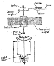
Figure 1. Moving Coil Instrument
The moving coil is wound with many turns of enamelled or silk covered copper wire. The coil is mounted on a rectangular aluminium former which is pivoted on jewellery bearings. The coils move freely in the field of permanent magnet. Most voltmeter coils are wound on metal frames to provide the required elctro-magnetic damping. Most ammeter coils however are wound on non-magnetic formers because coil turns are effectively shorted by the ammeter shunt. The coil itself therefore provides electromagnetic damping.
Torque Equation
The torque of moving coil instrument is given by
Deflection torque is Td = NB l dI = GI
Where G is constant
The spring control provides a restoring (controlling torque Td = K
For final steady deflection Tc = Td
Or GI = K
Final steady deflection  = G/K I
Current I = Kd 
Kd = K/G = constant
Example
A permanent magnet moving coil instrument has a coil of dimensions 15mmX12mm. The flux density in the air gap is 1.8 x 10 -3 Wb/m2 and the spring constant is 0.14 x 10 -6 Nm/rad. Determine the number of turns required to produce an angular deflection of 90 degrees when a current of 5mA flows through the coil.
Solution:
Deflection  =90 = π/2
At equilibrium
Td = Tc
NBI dl = K
Number of turns N = K / Bl. dI = 0.14 x 10 -6 x π/2 / 1.8 x 10 -3 x 15 x 10 -3 x 12 x 10-3 x 5 x 10 -3 = 136
Key Takeaways:
A measuring instrument in which current or voltage is determined by the couple on a small coil pivoted between the poles of a magnet with curved poles, giving a radial magnetic field.
2.1.3 Thermal Induction
|
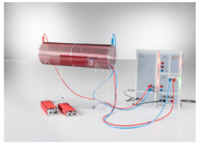
Figure 2. Measurement of induced voltage
In the experiment the induction coils with different areas and numbers of turns are arranged in a cylindrical field coil through which alternating currents of various frequencies, amplitudes and signal forms flow. In the field coil, the currents generate the magnetic field
B = μ0. N2 / L2.I
Where μo = 4π x 10 -r Vs/ Am (permeability)
and I(t) is the time-dependent current level, N2 the number of turns and L2 the overall length of the coil.
Key Takeaways:
The instrument whose working depends on the heating effects of the measuring current is known as the electrothermal or electrothermic instrument.
2.1.4 Rectifier type
Rectifier instruments are used for ac measurements by using a rectifier to convert ac into unidirectional dc and then to use d.c meter to indicate the value of rectified a.c. This method is attractive because PMMC has higher sensitivity than either the electrodynamometer type or the moving iron instruments.
Rectifier instruments are suited for measurements on communication circuits and other light current work where the voltages are low and resistance is high.
Key Takeaways:
Rectifier type instruments are used for measurement of ac. voltages and currents by employing a rectifier element, which converts a.c to a unidirectional d.c and then using a meter responsive to d.c to indicate the value of rectified a.c.
2.2.1 Dynamometer
It consists of a fixed coil FF (split into two parts) which carries the current of the circuit under test. So, the magnetic field produced by this coil is proportional to the main current.
|
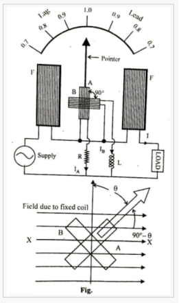
Figure 3. Dynamometer
The identical pressure coils A and B pivoted on a spindle constitutes the moving system. Pressure coil A has a non-inductive resistance R which is connected in series with it, and coil B has a highly inductive choke coil L which is connected in series with it. The two coils are connected across the voltage of circuit. The value of R and L are so adjusted that the two coils carry the same value of current at normal frequency i.e. R= WL.
The current through the coil A is in phase with the circuit voltage while that through the coil B legs the voltage by an angle ẟ which is nearly equal to 90°. The angle between the planes of coils is equal to δ.
Theory:
Let the current through coil B lags the voltage by exactly 90˚.
The field of the two fixed coils is uniform and in the direction of arrow. The torque on each coil for a given coil current will be maximum when the coil is parallel to the filed that is along XX. When the system power factor angle is φ, the coils take up a position of equilibrium displaced θ from the vertical. Then the torque due to the two coils must be equal and opposite.
Now since the current in coil A is in phase with the system voltage, the field in which it moves is proportional to the system current, then coil A is essentially a wattmeter movement displaced 90˚- θ from the maximum torque position. Then the torque of A is given by
TA=KVI cos φ cos (90˚- θ) where k is a constant. Similarly, since the current in coil B lags 90° on the system voltage, coil B is in a sine meter movement displaced θ from the maximum torque position. Then torque on B is. TB = KVI sin φ cos θ Hence at equilibrium TA = TB i.e. KVI cos φ cos (90˚- θ) KVI sin φ cos θ or, sin φ cos θ = cos φ sin θ or, tan θ = tan φ or, θ = φ therefore, the deflection of the instrument is a phase angle of the circuit. |
Key Take aways:
A dynamometer, or "dyno" for short, is a device for measuring force, moment of force (torque), or power.
2.2.2 Moving iron single and three phase power factor meters
The general circuit diagram of single- phase electrodynamometer power factor meter is given below.
|
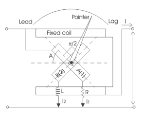
Figure4. Single Phase Power factor meter
The pressure coil is split into two parts one is purely inductive another is purely resistive as shown in the diagram. At present the reference plane is making an angle A with coil 1 and the angle between both the coils 1 and 2 is 90o.
Thus, the coil 2 is making an angle (90o + A) with the reference plane.
Consider the electrical resistance connected to coil 1 be R and inductor connected to coil 2 be L. During measurement of power factor, the values of R and L are adjusted so that R = wL so that both coils carry equal magnitude of current. Therefore, the current passing through the coil 2 is lags by 90o with reference to current in coil 1 as coil 2 path is highly inductive in nature.
Derivation for power factor meter.
Now there are two deflecting torques one is acting on the coil 1 and another is acting on the coil 2. The coil winding is arranged such that the two torques produced, are opposite to each other and therefore pointer will take a position where the two torques are equal.
The mathematical expression for the deflecting torque for coil 1-
T1 = KVI M cos A sin B
Where M is the maximum value of mutual inductance between the two coils,
B is the angular deflection of the plane of reference.
Now the mathematical expression for the deflecting torque for coil 2 is-
T2 = KVIM cos (90-A) sin(90+B) = KVIM sin A cos B
At equilibrium we have both the torque as equal thus on equating T1=T2 we have A = B.
The deflection angle is the measure of phase angle of the given circuit. The phasor diagram is also shown for the circuit such that the current in the coil 1 is approximately at an angle of 90o to current in the coil 2.
|
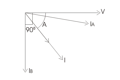
Figure 5. Phasor Diagram
Three Phase Power Factor:
A dynamometer type three-phase power factor meter gives correct readings only when the load is balanced.
It consists of two fixed coils FF connected in series in one of the phases and carries the line current as shown in the figure.
|
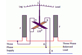
Figure 6. Three Phase Power Meter
The two moving coils A and B are fixed with their planes 120° apart and connected across the two remaining phases respectively through resistances which are high as shown in the figure.
When the three-phase power factor meter is connected in the circuit, under balanced load conditions, the angle through which the pointer is deflected from the unity power factor position is equal to the phase angle of the circuit, because the two moving coils are fixed 120° apart. The deflections in three phase power factor meters are independent of frequency and waveform since the currents in the two moving coils are affected in the same way by any change of frequency.
Key Takeaways:
The frequency meter consists one inductive and one resistive coil. When the frequency of the signal varies from standard frequency, the current distribution across the coils becomes changes.
2.2.3 Resonance
|
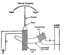
Figure 7. Electrical resonance type
It consists of fixed coil which is connected across the supply whose frequency is to be measured. This coil is called magnetizing coil. The magnetizing coil is mounted on laminated iron core. The iron core has cross-section which varies gradually over length being maximum near the end where the magnetizing coil is mounted and minimum at the other end. A moving coil is pivoted over this iron core. A pointer is attached to the moving coil. The terminals of the moving coil are connected to suitable capacitor C. There is no controlling force.
The operation of the instrument can be understood from three phasor diagrams (a), (b), (c). The magnetizing coil carries current I and this current produce flux ɸ. Flux ɸ being alternating in nature induces emf e in the moving coil. This emf lags behind the flux by 900. The emf induced circulates current I in the moving coil. The phase of this current I depend on L and capacitance.
|
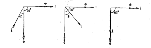
Figure 8. Phasor diagram for electrical resonance
In fig(a) the circuit of the moving coil is assumed to be inductive and therefore current I lag behind emf e by angle α. The torque acting on the moving coil is
Td α Ii cos(90+α)
In fig(b) the moving coil is assumed to be capacitive and therefore current I lead emf by angle β and the deflecting torque is
Td α Ii cos(90-β)
In fig (c) the inductive reactance is supposed to be equal to capacitive reactance therefore the circuit is in resonance. Thus, the moving coil circuit is purely resistive and so the current I in phase with emf e. This is because inductive reactance XL = 2 πf L =Xc= 1/2πfC. Therefore, the net reactance of the circuit is zero.
The deflecting torque is therefore
Td α Ii cos 90 =0
Hence the deflecting torque on the moving coil is zero when the inductive reactance equals capacitive reactance.
Key Takeaways:
The electrical resonance type frequency meter measures the frequency of these supply mains
2.2.4 Moving coil and moving iron frequency meters
Moving Iron Frequency Meter
|
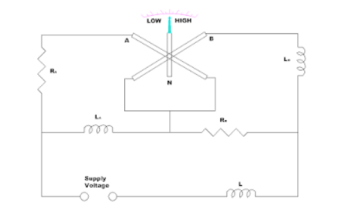
Figure 9. Moving Iron Frequency meter
This meter depends on the variations in an electric current drawn by inductive and non-inductive circuits connected in parallel. The current flows from these circuits when the frequency changes its value.
This meter consists of two fixed coils A and B that their magnetic axes are perpendicular to each other. A long and soft iron needle in pivoted at their centres. This circuit remains balanced at the supply frequency to be measured. Coil A consists of a series resistance Ra and a reactance La in parallel and the coil B consists of a series resistance Rb and a reactance Lb in parallel. The series inductance helps to suppress higher harmonics in the current waveform which helps to minimize the waveform errors in the indication of the instruments.
When the supply is connected to the meter, the current pass through the coils A and B and these two coils produce opposing torques. When the supply frequency increases then the current of the coil A increases and decreases in the coil B. The iron needle lies more nearly to the magnetic axis of the coil A. For low frequencies, the current of coil B increases and the current of the coil A decreases.
Moving coil frequency meter
The main principle of working of Weston type frequency meter is that “when an current flows through the two coils which are perpendicular to each other, due to these currents some magnetic fields will produce and thus the magnetic needle will deflects towards the stronger magnetic field showing the measurement of frequency on the meter”.
|
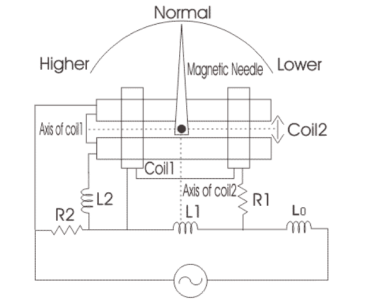
Figure 10. Moving coil frequency meter
Axis of both coils are marked as shown. Scale of the meter is calibrated such that at standard frequency the pointer will take position at 45o. Coil 1 contains a series resistor marked R1 and reactance coil marked as L1, while the coil 2 has a series reactance coil marked as L2 and parallel resistor marked as R2. The inductor which is marked as L0 is connected in series with the supply voltage in order to reduce the higher harmonic means here this inductor is working as a filter circuit. Let us look at the working of this meter.
Now when we apply voltage at standard frequency then the pointer will take normal position, if there increase the frequency of the applied voltage then we will see that the pointer will moves towards left marked as higher side as shown in the circuit diagram. Again, we reduce the frequency the pointer will start moving towards the right side, if lower the frequency below the normal frequency then it crosses the normal position to move towards left side marked lower side as shown in the figure.
Key Takeaways:
The moving iron instrument is used for measuring both the direct and alternating current whereas the moving coil is used for the DC measurement.
2.3.1 Voltmeter multipliers
|
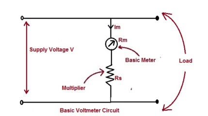
Figure 11. Voltmeter Circuit
A PMMC Instrument can be used as voltmeter by just connecting a series resistance with the moving coil. This series resistance is called Voltmeter Multiplier.
There are two main functions of voltmeter multiplier:
1) It limits the current through the PMMC moving coil to a value less than full scale deflection current and thus prevents moving coil from being damaged.
2) It minimizes the flow of current through the voltmeter and thus do not alter the circuit current whose voltage is to be measured. Ideally the resistance of voltmeter should be infinite.
The value of multiplier required to extend the voltage range is calculated as below. Let, Im = Ifs = Full scale deflection current of meter Rm = Internal resistance of meter Rs = Multiplier resistance Vm = Voltage across the moving coil V = Full range voltage of meter
Vm = ImRm ……………….(1) and V = Im(Rm + Rs) ………….(2) Dividing equation (2) by (1) we get, V/Vm = 1 + Rs/Rm Thus, m = Multiplying Factor = 1 + Rs/Rm The term V/Vm is called Multiplying Factor of Voltmeter. |
2.3.2 Ammeter shunt
Definition: The ammeter shunt is the device which provides the low resistance path to the flow of current. It connects in parallel with the ammeter.
Consider the circuit used for measuring the current I. The circuit has ammeter and shunt which is connected parallel to each other. The ammeter designs for measuring the small current say, Im. The magnitude of the current I pass through the meter is very high, and it will burn the meter. For measuring the current I the shunt is required in the circuit. The following expression calculates the value of the shunt resistance.
|
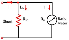
Figure12. Basic Ammeter circuit
As the shunt connects in parallel with the ammeter, thus the same voltage drop occurs between them.
Ish Rsh = Im Rm
Rsh = ImRm/Ish
The shunt current is Ish = I -Im
Therefore, the equation of shunt resistance is given as,
Rsh = ImRm/ I -Im
I/Im-1 = Rm/Rsh
I/Im -1 = Rm/Rsh
I/Im = Rm/Rsh +1
Example
The ratio of the total current to the current requires the movement of the ammeter coil is called the multiplying power of the shunt.
The multiplying power is given as, m=I/Im
The resistance of shunt becomes
m=1+Rm/Rsh
Rsh = Rm/m-1
Key Takeaways:
The resistance is required to be connected in series with the basic meter to use it as a voltmeter. This series resistance is called a multiplier.
2.3.3 Current Transformers
Construction of Current Transformer
The core of the current transformer is made of lamination of silicon steel. For high degree of accuracy, the Permalloy or Mumetal is used for making cores. The primary windings of the current transformers carry the current, which is to be measured, connected to the main circuit. The secondary windings of the transformer carry the current proportional to the current to be measured, connected to the current windings of the meters or the instruments.
The primary and the secondary windings are insulated from the cores and each other. The primary winding is a single turn winding called bar primary and carries the full load current. The secondary winding of the transformers has many turns.
|
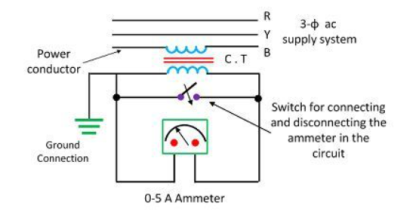
Figure 13. Current Transformer Construction
2.3.4 Potential Transformer
|
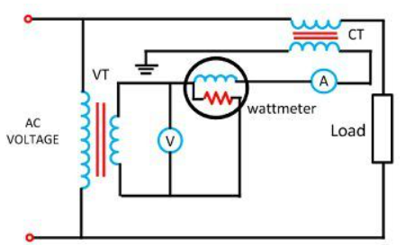
Figure 14. Potential Transformer Construction
The potential transformer is connected in parallel with the circuit. The primary windings of the potential transformer are directly connected to the power circuit where voltage is measured. The secondary terminals of the potential transformer are connected to the measuring instrument like the voltmeter, wattmeter, etc.
The secondary windings of the potential transformer are magnetically coupled through the magnetic circuit of the primary windings. The primary terminal of the transformer is rated for 400V to several thousand volts, and the secondary terminal is always rated for 400V. The ratio of the primary voltage to the secondary voltage is termed as transformation ratio or turn ratio.
Key Takeaways:
C.T. is basically used for the measurement of high currents. A P.T. is usually used for the measurement of high voltages.
References:
- Elements of Electronic Instrumentation and Measurement – by Carr
- Basic Electrical, Electronics and Measurement Engineering Paperback – 1 January 2019 by U.A Bakshi and A.P Godse.
- Electrical and Electronic Measurement and Instrument Paperback R.K Rajput
- Electrical & Electronic Measurements B. P. Patil, Pooja Mogre (Bisen)
- Electronic Measurements and Instrumentation by A.K. Sawhney


