Unit – 5
Introduction of passive filter
Filters are those electrical circuits which perform signal processing functions, to remove unwanted frequency components.
[I]. Classification of Passive Filters
Passive filters are made up of passive components such as resistors, capacitors and inductors, and have no amplifying elements such as transistors, op-amps etc. so have no signal gain. Therefore, the output level is always less than the input.
Filters are so named according to the frequency range of signals that they allow to pass.
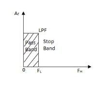
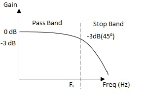
(a) Low Pass Filter: -These filters reject all frequencies above a specified value called the cut off frequency.
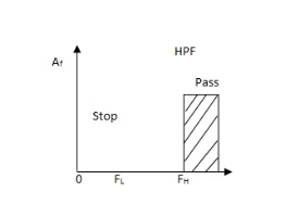
(b). High Pass Filter: -These filters reject all frequencies below the cut off frequency.
(c). Band Pass Filter: -These filters allow signals falling within a certain frequency band and blocks all the frequencies outside this band.
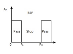
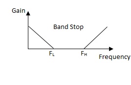
(d). Band Stop Filter: -These filters reject transmission of a limited band of frequencies but allows the transmission of all other frequencies.
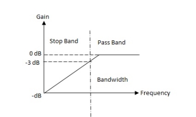
The figure below gives the ideal gain v/s frequency response of above all mentioned types of filters.
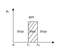
A BPF is usually obtained by series connections of LPF with a HPF, where FL of HPF < FH of LPF.
A BSP may be obtained by parallel connections of LPF with a HPF, where FH of HPF > FL of LPF.
For RC LPF the reactance of ‘C’ is very high at low frequency so, capacitor acts as open circuit and blocks i/p signal Vi until cut-off frequency is reached.
Cut-off frequency for a LPF is that frequency at which the voltage at output equals 70.7% of input voltage ( -3 dB point).
LPF are used to filter noise from circuit.
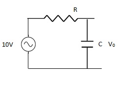 Q –A LPF circuit consisting of a resistor of 40KΩ in series with capacitor 47nF across a 10V sinusoidal supply. Calculate VO at frequency 1Kz?
Soln:
R = 40KΩ
C = 47nF
Vi = 10V
F = 1000 Hz
For LPF,
Capacitive Reactance is XC
The output voltage is given as
VO = Vi
XC =  =
= 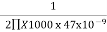
XC = 3.386KΩ
VO = 
=10 x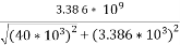
= 10 x
 VO = 0.843 V
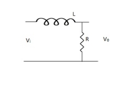
(b) RL LPF
FC = R / 2nt
VO = Vi
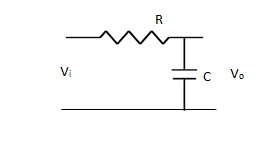 A Basic LPF circuit can be designed using passive elements R, L and C. The circuit is having single ‘R’ in series with capacitor ‘C’.
For RC LPF
VO = = Vi x  fC = 1 / 2∏RC
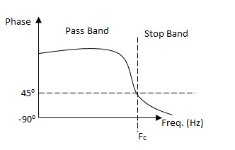
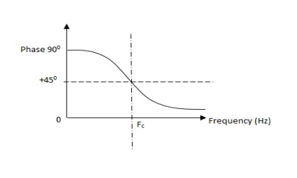
But Z =  Phase shift φ = -cot(2∏FC)
And XC =
VO – output voltage
Vi – input voltage
Z – Impedance
XC – Capacitive Reactance
FC – cut off Frequency
For RC LPF the reactance of ‘C’ is very high at low frequency so, capacitor acts as open circuit and blocks i/p signal Vi until cut-off frequency is reached.
Cut-off frequency for a LPF is that frequency at which the voltage at output equals 70.7% of input voltage ( -3 dB point).
LPF are used to filter noise from circuit.
 Q –A LPF circuit consisting of a resistor of 40KΩ in series with capacitor 47nF across a 10V sinusoidal supply. Calculate VO at frequency 1Kz?
Soln:
R = 40KΩ
C = 47nF
Vi = 10V
F = 1000 Hz
For LPF,
Capacitive Reactance is XC
The output voltage is given as
VO = Vi
XC =  =
= 
XC = 3.386KΩ
VO = 
=10 x
= 10 x
 VO = 0.843 V
(b) RL LPF
FC = R / 2nt
VO = Vi
Comparison of RL – RC circuits
- RC circuit occupy small space. It is not possible to fabricate inductors on surface of semiconductor chip.
- The response of charging and discharging of RL circuit is not proper.
- Capacitors are less expensive.
- RC- circuit is used in high time constant application. While RL used in low time constant applications.
 Q – An RL LPF consists of 5.6mH coil a 3.3 KΩ resistor. The output voltage is taken across resistor. Calculate the critical frequency?
Soln: Given:
L = 5.6 x 10⁻³ H
R = 3.3 x 10³Ω
For RL LPF
F = =
= 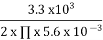
F = 93.78 KHz
Q – A sinusoidal voltage with peak to peak value of 10 V is applied to an RC LPF. If reactance at input is zero, find output voltage?
Soln:
VO = 
XC = 
F = XC = 0, F ->∞
Hence, VO = 0V.
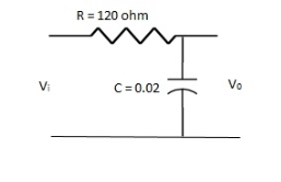 Q .An RC – LPF consists of 120 Ω resistor and 0.02 µF capacitor. The output is taken through capacitor. Calculate the critical frequency?
For RC LPF FC is given as
FC= =
=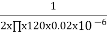
FC = 66.31 KHz
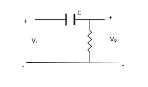 (a). The RC – HPF circuits is shown below, which is having capacitor at input and resistor at output.
Reactance of capacitor is very high at low frequency.
XC =
 XC when F ( C acts as open circuit )
XC when F ( C acts as short circuit )
FC = 
Phase shift = Cot 
VO =Vi
VO = Vi
At low F: XC ->∞ VO = 0
At high F: XC -> 0 VO = Vi
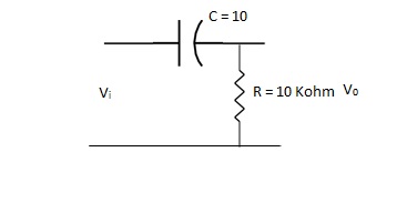 Q. An RC HPF with input capacitor 10nf and the output resistor of 10K Ω. Find the cut off frequency.
Soln:
FC = =
= 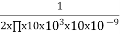
FC = 15.915 Hz
Q. Calculate the break point (FC) for a simple passive HPF consisting of 82pF capacitor connected in series with 240 KΩ resistor?
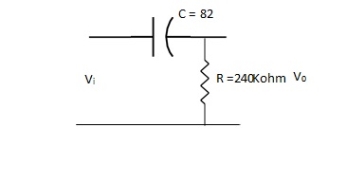 Soln:
Soln:
FC = =
= 
FC = 8KHz
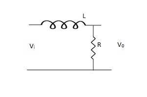
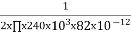
(b). RL – HPF :
The basic RL HPF is shown below. The inductors pass low frequency signals with very little resistance, and offers great resistance to high frequency signals.
VO = 
FC = 
Q. For a RL HPF consists of 470Ω resistor and 600 mH coil output is taken across coil. Calculate the cut off frequencies.
Soln:
FC =  =
= = 125 Hz
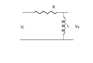
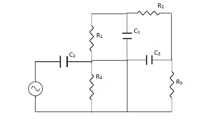
 It can be designed by making a series connection of HPF with a LPF. The Basic circuit is shown below.
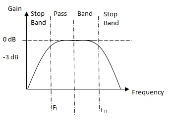
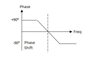
Fig. Frequency response and phase shift Put
FC = 1 / 2∏RC C2 = 1 / 2∏FHR
C1 = 1 / 2∏FLR FR = 
FL = lower -3dB cut off frequency
FH= upper -3dB cut off frequency
Band width (BW) = FH - FL
USES
1>. The BPF has its applications in wireless communication at transmitter and receiver.
2>. It is also used in optical communication.
3>. For reducing the signal to noise ratio at the receiving end.
Q. The value of capacitor C1 required to give a cut off frequency fL = 1KHz and value of resistor is 10K for the BPF. The value of capacitor C2 and higher cut off frequency (FH) is 30 KHz with resistor 10KΩ. Also calculate the central resonate frequency?
Soln: Given values for HPF
FL = 1000 Hz, R1 = 10 x 103Ω
C1 =  =
= = 15.9nF
For LPF,
FH = 30 x 103 Hz, R2 = 10 x 103Ω
C2 = =
= = 530nF
Central resonate frequency,
Fr = 
= 
Fr = 5.477 KHz
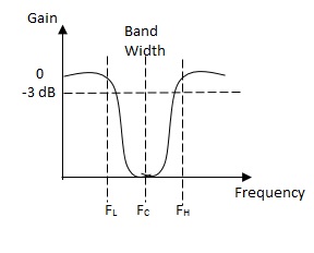
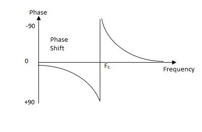
Band Stop Filter (BSF) OR Notch FILTER
A notch filter is a Band Stop filter with a narrow band stop bandwidth. These filters are used to attenuate a narrow range of frequencies.
FC = 1 / 2∏RC or FR = 
 R = 1 / 2∏FCC
Applications of BSF
(i). In telephone technology it is used as noise reducer.
(ii). Widely used in guitar amplifiers.
(iii). For reducing unwanted harmonics.
(iv). Used to reduce static on radio.
(v). In image signal processing.
(vi). Used in biometric instruments like ECG for removing line noise.
Calculation of some basic parameters for T and ∏ section filters
Basic circuit for the calculation of few parameters such as impedance (Zo), and attenuation and phase constants are shown below. Here we consider a symmetrical network.
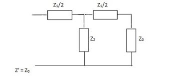
(i). Calculating Zo for T – section fig (a).
Zo = 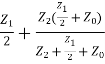
Z0 =  +
+
4Z20 + 4Z2Z0 + 2Z1Z0 = Z21 + 4Z1Z2 + 2Z0Z1 + 4Z0Z2
4Z02 = Z12 + 4Z1Z2
Z02 = Z12/4 + Z1Z2
For T-section Z0T =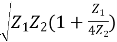 -(1)
-(1)
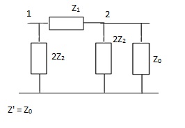
(ii). Calculating same for ∏-section network
Zo=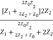
Z0 =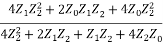
4Z1Z22 = Z02Z1 + 4Z02Z2
Z02 = 
Z0∏ =  - (2)
- (2)
From (1) & (2)
Z0T.Z0∏ = Z1Z2
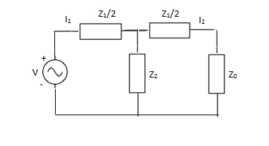 (iii). Attenuation and phase constant for symmetrical T-section shown below.
Applying KVL,
V = I1( +
+ ) – I2Z2
0 = -I1Z2 + I2( + Z2 + Z0)
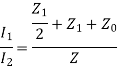
Let  = eᵞ
= eᵞ
Where ᵞ = Propagation constant
ᵞ = α + jβ
α : attenuation constant(nepers)
β : phase constant(radians)
eᵞ = 
Z0 = Z2(eᵞ - 1)- 
But from eqn (1)
ZOT2 = Z12/4 + Z1Z2
Eliminating Z0 we get
Z2(eᵞ- 1)2 – Z2 eᵞ = 0
 = 1 +
= 1 + 
Coshᵞ = 1 + 
Since, Sinh =
=
Sinh =
= 
Sinh =
=  - (3)
- (3)
But ᵞ = α + jβ
Sinh ( +
+  )=
)= 
Expanding above equation
Sinh . Cos
. Cos + jCosh
 . Sin
. Sin =
= 
When Sinh . Cos
. Cos = 0
= 0
α = 0, β≠ 0. Sin =
= 
For pass band
α = 0, β = 2Sin-1 | - (4)
When cos  = 0
= 0
α≠ 0, β = (2n - 1) ∏
Cosh  =
= 
For Stop Band:
α = 2 cos h-1 , β = ∏ - (5)
Reference
- Engineering Circuit Analysis”, by W H Hayt, TMH Eighth Edition
- “Network analysis and synthesis”, by F F Kuo, John Weily and Sons, 2nd Edition.
- “Circuit Theory”, by S Salivahanan, Vikas Publishing House 1st Edition, 2014
- “Network analysis”, by M. E. Van Valkenburg, PHI, 2000
- “Networks and Systems”, by D. R. Choudhary, New Age International, 1999
- Electric Circuit”, Bell Oxford Publications, 7th Edition.


