Unit - 3
Control of Frequency and Voltage
The process by which the speed of a turbine or a generator is kept constant under varying condition of load is called governing system of the turbine. It is an automatic process.
Turbine governing is a procedure of controlling the flow rate of steam in a turbine so as to maintain its constant speed of rotation. Load variation plays a significant role in the performance of a turbine.
Speed governor is the primary tool for the Load Frequency Control (LFC). Figure below depicts an arrangement of a speed governing system for steam turbines operate to control the generator output to maintain constant frequency.
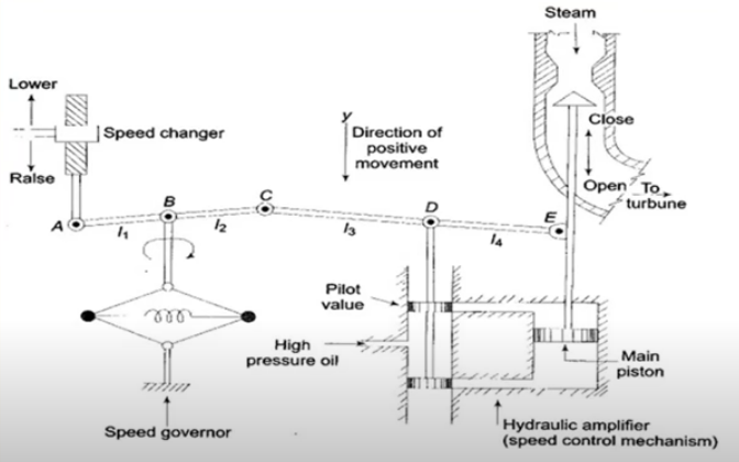
Parts of a speed governing system
It is the heart of the system which senses speed change. As speed increases the fly ball moves outwards & point B as shown in the diagram moves downward. When the speed decreases the reverse process happens.
2. Hydraulic Amplifier
This consists of a pilot valve & main piston and helps to convert low power pilot valve movement to high power piston valve movement. It is required to open or close the steam valve in case of high-pressure steam.
3. Linkage Mechanism
It allows movement of the control valve with change in speed.
4. Speed Changer
It ensures a steady state power output for the turbine setting. Downward movement of the speed changer opens up the upper pilot valve, there by admitting more steam to the turbine under steady conditions which means more steady power output
Adjustment of Governor Characteristics
The control of load & system frequency depends upon the governor of the prime movers. The characteristics of the speed governor system are as depicted in the figure below-

For Stable operation of the generator, governors are designed so as to permit the speed to go down as the load is increased. Slope of the curve depicts speed regulation (R) typically governors have a speed regulation of 5-6% from 0 to full load.
% Regulation = (Change in Frequency/Change in Power Output) *100
Key Takeaway
The process by which the speed of a turbine or a generator is kept constant under varying condition of load is called governing system of the turbine. It is an automatic process. Turbine governing is a procedure of controlling the flow rate of steam in a turbine so as to maintain its constant speed of rotation. Load variation plays a significant role in the performance of a turbine.
In the droop speed control mode, the speed will decrease by a fixed percentage when the generator is loaded from no-load to full load. This provides a stable working point for each load in case of parallel operation.

The droop speed is the drop in speed with load and is a characteristic of the governor or speed regulator for the prime mover. When used as a standalone generator this will determine the drop in frequency. It is typically 2-4% at full load.
When used in conjunction with other generators (in parallel) then the generators sets will share the total load based on the droop characteristic. If they are identical then they will share equally.

Typical droop characteristic
Two generators using droop control to provide max power at 60Hz. One has a 63.4 Hz reference and the other 61.8Hz reference for both to deliver full power at 60 Hz.

The pic below shows typical speed droop control. At 25% load the speed reference would have to be 60.6 Hz (1% droop) to achieve 60Hz and this would have to be 62.4 Hz (4% droop) to achieve 60 Hz at full load.
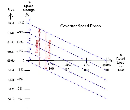
Thus, the aim of droop control is to adjust the governor speed references to firstly achieve the correct system frequency and secondly share load in accordance with the respective generators contribution in terms of its generating capacity. This allows generators of different sizes to share the total load unlike isochronous operation which does not.
Key Takeaway
The aim of droop control is to adjust the governor speed references to firstly achieve the correct system frequency and secondly share load in accordance with the respective generators contribution in terms of its generating capacity.
In a power system, the frequency deviations are mainly due to real power mismatch between generation and load, where as voltage variations are due to reactive power imbalance in the system. The reactive power is produced close to requirements as involves only capital cost but no fuel cost and it is not exported on the lines to avoid large transmission losses. However, for successful operation of a power system active power balance can be achieved by controlling the generation and it is called automatic generation control (AGC). The control loops of these two parameters, therefore, assumed to be decoupled. Moreover, a sustained frequency deviation directly affects power system operation, security, reliability, and efficiency by damaging equipment, degrading load performance, overloading transmission lines, and undesirable triggering of the power system protection devices.

The AGC is a significant control process that operates constantly to balance the generation and load in power systems at a minimum cost. The AGC is responsible for frequency control and power interchange, as well as economic dispatch. AGC provides an effective mechanism for adjusting the generation to minimize frequency deviation and regulate tie-line power flows. The AGC system realizes generation changes by sending signals to the under-control generating units. The performance of an AGC system is highly dependent on how quickly and effectively generating units respond to the commands. However, the response characteristics of generating unit are associated with numerous factors, such as type of unit, fuel, control strategy, and operating point. Since the frequency generated in the power system network is proportional to the rotation speed of the generator, the problem of frequency control may be directly converted into a speed control problem of the turbine generator unit. This is initially done by augmenting a governing mechanism that senses the generator speed, and adjusts the input valve for changing the mechanical power output to track the load change and for restoring nominal frequency value.
Function of AGC System in an Interconnected Power System
In modern AGC schemes, the control actions are usually determined for each control area of a power system at dispatch centre. The figure below describes the functional diagram of a typical AGC system. The power system is interconnected via tie-lines. In a control area all the generators not taking parts in AGC rather than only few generators contribute for AGC. The functional diagram of AGC system is consisting of control areas, economic dispatch centre (EDC) and various components of AGC system. The EDC receives daily schedule for generators, dispatch the power economically and updates the schedule of power units in every 5 minutes.
Information pertaining to tie line flows, system frequency, and unit MW loadings is telemetered to dispatch centre, where the control actions are determined by a digital computer. However, the control equipment at the power plants changes the reference set-points of the units up or down in proportion to the pulse length. With the measurement of tie-line flow, its deviation, frequency deviation in ACE is obtained and raise/lower control signal is given to the generation units (units which are on AGC) in every 1-2 sec for control of power units.

Key Takeaway
In modern AGC schemes, the control actions are usually determined for each control area of a power system at dispatch centre. The figure below describes the functional diagram of a typical AGC system.
In static excitation systems, the field voltage is obtained directly by rectifying (using controlled rectifiers) the output voltage of the main synchronous generator. Therefore, in these systems, the generator is practically self excited with some initial voltage being obtained temporarily using station batteries (called field flashing). In static excitation systems, it is necessary to use slip rings to convey the field voltage (output of the controlled rectifier) to the rotating field winding of the main generator

An exciter is usually controlled so as to regulate generator terminal voltage. The general structure of a voltage regulator system is shown on the right. While the regulator maintains voltage close to the reference value, an operator may also slowly change the reference value itself if a change in reactive power is desired. A typical excitation system also utilizes limiting signals which change the reference voltage so that the generator works within its reactive power capability.
Overhead Lines: Absorb or supply reactive power based on loading conditions. Overhead transmission lines may draw or supply reactive power depending on the loading conditions. We saw in Module 2 that a line draws reactive power if loading is higher than the Surge Impedance Loading and generates reactive power otherwise.
Cables: Surge Impedance of cables can be quite high (higher than the thermal limits) and they are typically loaded much below their Surge Impedance Loading. This leads to significant generation of reactive power and overvoltage problems if cable length is greater than 30-40 km.
Transformers: Transformers generally absorb reactive power due to shunt magnetizing and series leakage reactances
Loads: Normally absorb reactive power.
Key Takeaway
In static excitation systems, the field voltage is obtained directly by rectifying (using controlled rectifiers) the output voltage of the main synchronous generator. Therefore, in these systems, the generator is practically self excited with some initial voltage being obtained temporarily using station batteries (called field flashing).
The system which is used for providing the necessary field current to the rotor winding of the synchronous machine, such type of system is called an excitation system. In other words, excitation system is defined as the system which is used for the production of the flux by passing current in the field winding. The main requirement of an excitation system is reliability under all conditions of service, a simplicity of control, ease of maintenance, stability and fast transient response.
The amount of excitation required depends on the load current, load power factor and speed of the machine. The more excitation is needed in the system when the load current is large, the speed is less, and the power factor of the system becomes lagging.
The excitation system is the single unit in which each alternator has its exciter in the form of generator. The centralised excitation system has two or more exciter which feeds the bus-bar. The centralised system is very cheap, but the fault in the system adversely affects the alternators in the power plant.
Types of Excitation System
The excitation system is mainly classified into three types. They are
- Rotor Excitation System
- Brushless Excitation System
Their types are explained below in details.
1. DC Excitation System
The DC excitation system has two exciters – the main exciter and a pilot exciter. The exciter output is adjusted by an automatic voltage regulator (AVR) for controlling the output terminal voltage of the alternator. The current transformer input to the AVR ensures limiting of the alternator current during a fault.
When the field breaker is open, the field discharge resistor is connected across the field winding so as to dissipate the stored energy in the field winding which is highly inductive.

The main and the pilot exciters can be driven either by the main shaft or separately driven by the motor. Direct driven exciters are usually preferred as these preserve the unit system of operation, and the excitation is not excited by external disturbances.
The voltage rating of the main exciter is about 400 V, and its capacity is about 0.5% of the capacity of the alternator. Troubles in the exciters of turbo alternator are quite frequent because of their high speed and as such separate motor driven exciters are provided as standby exciter.
2. AC Excitation System
The AC excitation system consists of an alternator and thyristor rectifier bridge directly connected to the main alternator shaft. The main exciter may either be self-excited or separately excited. The AC excitation system may be broadly classified into two categories which are explained below in details.
a. Rotating Thyristor Excitation System
The rotor excitation system is shown in the figure below. The rotating portion is being enclosed by the dashed line. This system consists an AC exciter, stationary field and a rotating armature. The output of the exciter is rectified by a full wave thyristor bridge rectifier circuit and is supplied to the main alternator field winding.

The alternator field winding is also supplied through another rectifier circuit. The exciter voltage can be built up by using it residual flux. The power supply and rectifier control generate the controlled triggering signal. The alternator voltage signal is averaged and compare directly with the operator voltage adjustment in the auto mode of operation. In the manual mode of operation, the excitation current of the alternator is compared with a separate manual voltage adjustment.
b. Brushless Excitation System
This system is shown in the figure below. The rotating portion being enclosed by a dashed line rectangle. The brushless excitation system consists an alternator, rectifier, main exciter and a permanent magnet generator alternator. The main and the pilot exciter are driven by the main shaft. The main exciter has a stationary field and a rotating armature directly connected, through the silicon rectifiers to the field of the main alternators.

The pilot exciter is the shaft driven permanent magnet generator having rotating permanent magnets attached to the shaft and a three-phase stationary armature, which feeds the main exciter field through silicon rectifiers, in the field of the main alternator. The pilot exciter is a shaft driven permanent magnetic generator having rotating permanent magnets attached to the shaft and a 3-phase stationary armature, which feeds the main’s exciter through 3-phase full wave phase-controlled thyristor bridges.
The system eliminates the use of a commutator, collector and brushes have a short time constant and a response time of fewer than 0.1 seconds. The short time constant has the advantage in improved small signal dynamic performance and facilitates the application of supplementary power system stabilising signals.
3. Static Excitation System
In this system, the supply is taken from the alternator itself through a 3-phase star/delta connected step-down transformer. The primary of the transformer is connected to the alternator bus and their secondary supplies power to the rectifier and also feed power to the grid control circuit and other electrical equipment.

This system has a very small response time and provides excellent dynamic performance. This system reduced the operating cost by eliminating the exciter windage loss and winding maintenance.
Key Takeaway
The amount of excitation required depends on the load current, load power factor and speed of the machine. The more excitation is needed in the system when the load current is large, the speed is less, and the power factor of the system becomes lagging.
The automatic voltage regulator is used to regulate the voltage. It takes the fluctuate voltage and changes them into a constant voltage. The fluctuation in the voltage mainly occurs due to the variation in load on the supply system. The variation in voltage damages the equipment of the power system. The variation in the voltage can be controlled by installing the voltage control equipment at several places likes near the transformers, generator, feeders, etc., The voltage regulator is provided in more than one point in the power system for controlling the voltage variations.
In DC supply system the voltage can be controlled by using over compound generators in case of feeders of equal length, but in the case of feeders of different lengths the voltage at the end of each feeder is kept constant using feeder booster. In AC system the voltage can be controlled by using the various methods likes booster transformers, induction regulators, shunt condensers, etc.,
Working Principle of Voltage Regulator
It works on the principle of detection of errors. The output voltage of an AC generator obtained through a potential transformer and then it is rectified, filtered and compared with a reference. The difference between the actual voltage and the reference voltage is known as the error voltage. This error voltage is amplified by an amplifier and then supplied to the main exciter or pilot exciter.

Thus, the amplified error signals control the excitation of the main or pilot exciter through a buck or a boost action (i.e., controls the fluctuation of the voltage). Exciter output control leads to the controls of the main alternator terminal voltage.
Application of the Automatic Voltage Regulator
The main functions of an AVR are as follows.
When there is a sudden change in load in the alternator, there should be a change in the excitation system to provide the same voltage under the new load condition. This can be done by the help of the automatic voltage regulator. The automatic voltage regulator equipment operates in the exciter field and changes the exciter output voltage, and the field current. During the violent fluctuation, the ARV does not give a quick response.
For getting the quick response, the quick acting voltage regulators based on the overshooting the mark principle are used. In overshoot mark principle, when the load increases the excitation of the system also increase. Before the voltage increase to the value corresponding to the increased excitation, the regulator reduces the excitation of the proper value.
Key Takeaway
The automatic voltage regulator is used to regulate the voltage. It takes the fluctuate voltage and changes them into a constant voltage. The fluctuation in the voltage mainly occurs due to the variation in load on the supply system.
At buses where reactive power demand increases, bus voltage can be controlled by connecting capacitor banks in parallel to a lagging load. Capacitor banks supply part of or full reactive power of load, thus reducing magnitude of the source current necessary to supply load. Consequently, the voltage drops between the sending end and the load gets reduced, power factor will be improved and increased active power output will be available from the source. Depending upon load demand, capacitor banks may be permanently connected to the system or can be varied by switching ON or OFF the parallel connected capacitors either manually or automatically. Following figure shows the single line diagram of a transmission line and its phasor diagram before the addition of the shunt capacitor and its phasor diagram.

Key Takeaway
At buses where reactive power demand increases, bus voltage can be controlled by connecting capacitor banks in parallel to a lagging load. Capacitor banks supply part of or full reactive power of load, thus reducing magnitude of the source current necessary to supply load.
STATCOM’s are characterized by a compact structure. Having the same available value of reactive power as SVC, STATCOM occupies much less space. In addition, they have better dynamics. These systems have not supplanted SVC. One of the reasons is the installation cost- despite continuous technological development. They are expensive compared with SVC. The first consists of voltage source inverter which is used as a voltage converter; the capacitor is the inverter load. Pulse Phase modulation is a convenient method for inverter control. It is required to maintain constant voltage in the capacitor which is the inverter load on the DC side. The below figure depicts a system of voltage controller.

VIS type STATCOM’s have been used in power systems as devices designed to cooperate with wind farms, irregular receipts, and also control the voltage in the system nodes. The other type of STATCOM is a device based on the current source inverter and it has been used in the power systems yet.
Key Takeaway
STATCOM’s are characterized by a compact structure. Having the same available value of reactive power as SVC, STATCOM occupies much less space. In addition, they have better dynamics.
A static VAR compensator is a parallel combination of controlled reactor and fixed shunt capacitor shown in the figure below. The thyristor switch assembly in the SVC controls the reactor. The firing angle of the thyristor controls the voltage across the inductor and thus the current flowing through the inductor. In this way, the reactive power draw by the inductor can be controlled.

The SVC is capable of step less adjustment of reactive power over an unlimited range without any time delay. It improves the system stability and system power factor. Most commonly used SVC scheme are as follows.
Advantage of Static VAR Compensator
Static VAR compensator has no rotating parts and is employed for surge impedance compensation and compensation by sectionalizing a long transmission line.
Key Takeaway
A static VAR compensator is a parallel combination of controlled reactor and fixed shunt capacitor shown in the figure below. The thyristor switch assembly in the SVC controls the reactor.
Tap Changing Transformer -Voltage variation in power systems is a normal phenomenon owing to the rapid growth of industries and distribution network. System voltage control is therefore essential for:
Adjustment is normally carried out by off-circuit tap changing, the common range being 5% in 2.5% steps. Daily and short-time control or adjustment is carried out by means of on-load tap changing gear.
Besides the above, tapping is also provided for one of the following purposes:
The principal tapping is one to which the rating of the winding is related. A positive tapping means more, and a negative tapping implies less turns than those of the principal tap. Tap Changing Transformer may be achieved in one of the three conditions, viz.
The taps may be placed on the primary or secondary side which partly depends on construction. If tappings are near the line ends, fewer bushing insulators are required. If the tappings are placed near the neutral ends, the phase-to-phase insulation conditions are eased. For achieving large voltage variation, tappings should be placed near the centres of the phase windings to reduce magnetic asymmetry. However, this arrangement cannot be put on LV windings placed next to the core (as in core type transformer) because of accessibility and insulation considerations. The HV winding placed outside the LV winding is easily accessible and can, thus, be tapped easily.
It is not possible to tap other than an integral number of turns and this may not be feasible with LV side tappings. For example, 250 V phase winding with 15 V/turn cannot be tapped closer than 5%. It is therefore essential to tap the HV windings which is advantageous in a step-down transformer. Some of the methods of locating tappings are depicted in the figure below-

Axial mmf unbalance is minimized by thinning out the LV winding or by arranging parts of the winding more symmetrically. For very large tapping ranges a special tapping coil may be employed. Tap Changing Transformer causes changes in leakage reactance, core loss, I2R loss and perhaps some problems in parallel operation of dissimilar transformers.
OFF Load Tap Changer
The cheapest method of changing the turn ratio of a transformer is the use of Off Load Tap Changer. As the name indicates, it is required to deenergize the transformer before changing the tap. A simple Off Load Tap Changer is shown in Fig. 3.68. It has eight studs marked one to eight. The winding is tapped at eight points. The face plate carrying the suitable studs can be mounted at a convenient place on the transformer such as upper yoke or located near the tapped positions on the windings. The movable contact arm A may be rotated by handwheel mounted externally on the tank.
If the winding is tapped at 2% intervals, then as the rotatable arm A is moved over to studs 1, 2; 2, 3; . . . 6, 7; 7, 8 the winding in circuit reduces progressively by it from 100% with arm at studs (1, 2) to 88% at studs (7, 8).
The stop F which fixes the final position of the arm A prevents further anticlockwise rotation so that stud 1 and 8 cannot be bridged by the arm. Adjustment of tap setting is carried out with transformer reenergized. For example, for 94% tap the arm is brought in position to bridge studs 4 and 5. The transformer can then be switched on.

To prevent unauthorized operation of an off-circuit tap changer, a mechanical lock is provided. Further, to prevent inadvertent operation, an electromagnetic latching device or microswitch is provided to open the circuit breaker so as to deenergize the transformer as soon as the tap changer handle is moved; well before the contact of the arm with the stud (with which it was in contact) opens.
On Load Tap Changer
On Load Tap Changing Transformer are used to change the turn ratio of transformer to regulate system voltage while the transformer is delivering load. With the introduction of On Load Tap Changing Transformer, the operating efficiency of electrical system gets considerably improved. Nowadays almost all the large power transformers are fitted with on load tap changer. During the operation of an on-load tap changer the main circuit should not be opened to prevent (dangerous) sparking and no part of the tapped winding should get short-circuited. All forms of on load tap changer circuits are provided with an impedance, which is introduced to limit short-circuit current during the tap changing operation. The impedance can either be a resistor or centre-tapped reactor. The On Load Tap Changing Transformer can in general be classified as resistor or reactor type. In modem designs the current limiting is almost invariably carried out by a pair of resistors.
On Load Tap Changing Transformer gear with resistor transition, in which one winding tap is changed over for each operating position, is depicted in Fig. 3.69. The figure also shows the sequence of operations during the transition from one tap to the next (adjoining) (in this case from tap 4 to tap 5). Back-up main contractors are provided which short-circuit the resistor for normal operation.
To ensure that the transition once started gets completed, an energy (usually a spring device) storage is provided which acts even if the auxiliary power supply happens to fail. In resistor-aided Tap Changing Transformer the current break is made easier by the fact that the short-circuit resistor causes the current to be opened to have unity power factor.

On Load Tap Changer control gear can be from simple push-button initiation to complex automatic control of several transformers operating in parallel. The aim is to maintain a given voltage level within a specified tolerance or to raise it with load to compensate for the transmission line voltage drop. The main components are an automatic voltage regulator, a time delay relay, and compounding elements. The time delay prevents unwanted initiation of a tap change by a small transient voltage fluctuation. It may be set for a delay unto 1 min.
At present tap changers are available for the highest insulation level of 1475 kV (peak) impulse and 630 kV power frequency voltage. Efforts are underway to develop tap changers suitable for still higher insulation levels. More compact tap changers with high reliability and performance are being made by employing vacuum switches in the diverter switch. Also, now thyristorized tap changers are available for special applications where a large number of operations are desired.
Key Takeaway
Tap Changing Transformer -Voltage variation in power systems is a normal phenomenon owing to the rapid growth of industries and distribution network
Power flow can be controlled by converting AC to DC with the help of thyristor bridges or voltage source converters & then re converting the DC to AC in the same way at another bus.
The converters are connected to the AC transmission system in shunt at 2 buses, if large distance is kept between the two buses, then high voltage DC transmission is obtained. This power flow is a function of converter firing angle & is independent of voltage phase angle as well as frequency at both ends. DC links embedded in an AC system are used to transfer power over long a distance which is otherwise difficult with the help of AC lines. DC links are also used to permit controlled interchange of power between two systems which are not connected synchronously to each other.
Key Takeaway
Power flow can be controlled by converting AC to DC with the help of thyristor bridges or voltage source converters & then re converting the DC to AC in the same way at another bus.
Phase Shifters are devices, in which the phase of an electromagnetic wave of a given frequency can be shifted when propagating through a transmission line. In many fields of electronics, it is often necessary to change the phase of signals. RF and microwave Phase Shifters have many applications in various equipments such as phase discriminators, beam forming networks, power dividers, linearization of power amplifiers, and phase array antennas. The major parameters which define the RF and microwave Phase Shifters are: frequency range, bandwidth (BW), total phase variance, insertion loss, switching speed, power handling (P), accuracy and resolution, input/output matching (VSWR) or return loss (RL), harmonics level.
Analog Phase Shifters
These are devices whose phase shift changes continuously with the control input and therefore offer almost unlimited resolution with monotonic performance. The most commonly semiconductor control elements used in analog Phase Shifters are varactor diodes. Varactor diode operates in a reverse-biased condition providing a junction capacitance that varies with applied voltage, and can be used as an electrically variable capacitor in a tuned circuit. • Varactor analog Phase Shifters can achieve a large amount of phase shift and high speed and require fewer diodes than digital phase shifters, but at the cost of decreased accuracy, relatively narrow bandwidth, and low input power levels (less than 1 W). • Schottky diodes are also used as variable elements in analog Phase Shifters, but they suffer from limited power handling capability and matching difficulty in broadband networks. Most usual methods to implement Phase Shifters are based on switched line, loaded line, and reflection theories.
Switched Line Phase Shifter
The Switched-Line approach is the most straightforward approach because it uses the simple time delay difference between two direct paths to provide desired phase shift. The switching elements in digital phase shifters are: mechanical switches (or relays), PIN diodes, Field Effect Transistors (FET), or microelectromechanical systems (MEMS). PIN diodes are commonly used in Phase Shifters due their high-speed switching time, low loss, and relatively simple bias circuits, which provides changes of PIN resistance approximately from 10 kilo-ohms to 1 ohm. The PIN diode switched line Phase Shifters can be classified as follow:
The standard switched-line Phase Shifter is using switched transmission line segments, getting different path length and determining in this way the amount of phase shift.
Key Takeaway
Phase Shifters are devices, in which the phase of an electromagnetic wave of a given frequency can be shifted when propagating through a transmission line. In many fields of electronics, it is often necessary to change the phase of signals. RF and microwave Phase Shifters have many applications in various equipments such as phase discriminators, beam forming networks, power dividers, linearization of power amplifiers, and phase array antennas.
References:
1. Power system Analysis-by John J Grainger William D Stevenson, TMC Companies, 4th edition.
2. The Power System Analysis and Design by B.R. Gupta, Wheeler Publishing
3. Power System Analysis by Hadi Saadat – TMH Edition.
4. Modern Power System Analysis by I.J. Nagaraj and D.P.


